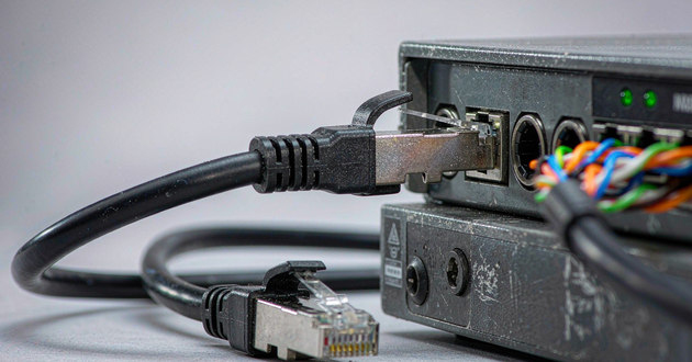
A reliable custom connector design starts before CAD release or tooling. The engineering team must define the interface, data rate, power load, pin assignment, shielding, PCB footprint, mechanical envelope, assembly process, environment and validation criteria as one system. If these inputs remain open when prototyping begins, the sample may fit the enclosure but still fail signal, thermal, EMI or production requirements.
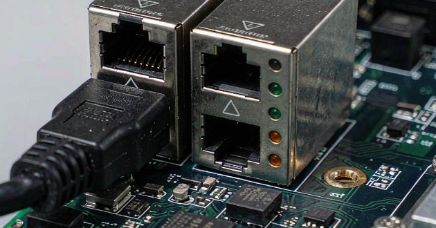
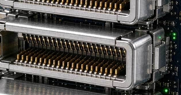
This checklist is intended for switches, routers, gateways, network interface cards, industrial Ethernet devices and other networking hardware that uses board-mounted RJ45, magnetic RJ45, SFP-family or application-specific connector structures. It helps hardware teams prepare a complete design and RFQ package before requesting samples.
Custom Connector Design Checklist: Start With the Decision Gate
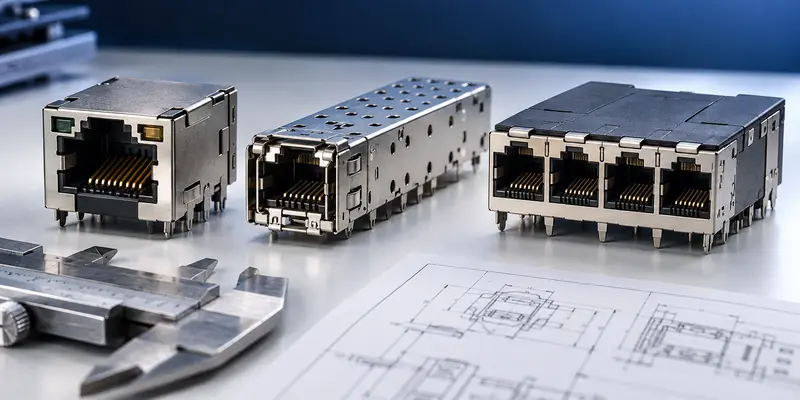
Before creating a new connector, determine whether the problem truly requires a full custom design. A standard connector is normally the lowest-risk choice when its electrical rating, mating interface, footprint, port orientation and mechanical retention already fit the product. A semi-custom solution may be enough when the equipment only needs a different LED arrangement, shield structure, light pipe, heat sink, pin assignment, mounting feature or port configuration.
A fully custom connector becomes reasonable when standard parts cannot meet several linked constraints. Examples include a fixed front-panel opening, an unusual PCB-to-panel distance, a high-density port arrangement, a required data-and-power combination, a nonstandard pinout, restricted airflow or a mating interface that must remain compatible with existing field hardware. The team should document the exact reason for customization. Otherwise, the project can absorb tooling cost and qualification work without solving a defined system problem.
Use a decision gate before design release:
| Decision question | Standard or modified connector may work when | Full custom review is justified when |
|---|---|---|
| Interface | The existing mating interface is acceptable | The mating geometry or pin arrangement is application-specific |
| PCB and panel fit | A catalog footprint and orientation fit the board | Board edge, enclosure and cable access impose a unique geometry |
| Electrical performance | Existing ratings cover the channel and power load | Signal, shielding or current requirements cannot be met together |
| Product features | Available LED, cage, shield or port options are sufficient | Several features must be integrated into one mechanical structure |
| Lifecycle | The part is available and suitable for the planned program | Supply continuity or product architecture requires a controlled design |
Electrical Requirements for Networking Hardware Connectors
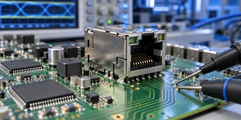
The electrical brief should describe the link rather than only naming a connector family. State the Ethernet speed or serial interface, PHY or module type, number of lanes or pairs, differential impedance target, pin assignment, grounding method and channel assumptions. For an RJ45 interface, clarify whether the project needs a standard jack or integrated magnetics. For SFP, SFP+, SFP28 or QSFP-family hardware, define the module interface, lane rate, port count and cage configuration.
Power requirements belong in the same brief. If the port carries PoE, provide the applicable power architecture, maximum operating current, conductor or contact allocation, expected ambient temperature and allowable temperature rise. Do not select contact geometry from a nominal wattage alone. Current distribution, contact resistance, PCB copper, magnetics, ventilation and the number of simultaneously powered ports all affect thermal behavior.
The following inputs should be frozen or clearly marked as provisional before a connector prototype is ordered:
| Electrical input | Information to provide |
|---|---|
| Protocol and speed | Ethernet generation, lane rate or other serial protocol |
| Mating interface | Plug, module or existing counterpart the connector must accept |
| Pin assignment | Signal pairs, grounds, power contacts, LEDs and reserved pins |
| Power load | Voltage, current, PoE requirement and simultaneous port loading |
| Impedance | Differential target and any single-ended requirement |
| Protection | ESD, surge, isolation and grounding expectations |
| Test target | Insertion loss, return loss, crosstalk or channel compliance criteria |
Connector Customization for Signal Integrity and EMI Control
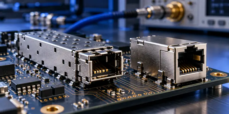
In high-speed networking hardware, the connector is part of the transmission channel. Its contact geometry, dielectric structure, pin assignment, shielding and PCB launch can introduce impedance discontinuities, insertion loss, return loss and crosstalk. A mechanically correct sample can therefore perform poorly after it is installed on the host board.
Effective connector customization begins with the complete path: PHY or switch ASIC, PCB traces, vias, connector contacts, cage or shield, mating module or cable and the return-current path. Differential pairs should remain geometrically balanced through the transition. Ground contacts and shield connections should provide a short, low-inductance return path. High-speed pairs should not be assigned beside noisy power or LED circuits without reviewing coupling risk.
The supplier should receive the proposed PCB stack-up, connector location, routing direction, nearby metalwork and relevant channel budget. When the connector is placed at the chassis boundary, shielding and chassis-ground strategy must also be coordinated with the enclosure. Treating the connector shield, digital ground and chassis ground as interchangeable can create EMI problems that are difficult to diagnose after the first board spin.
Simulation can identify likely discontinuities before metal and plastic tooling is released, but the simulation boundary must be defined. Confirm whether the model includes only the contact system or also the PCB launch, vias and mating interface. After samples are available, correlate the modeled structure with board-level measurements under the intended fixture and channel conditions.
Custom Connector Solutions for Mechanical and PCB Integration
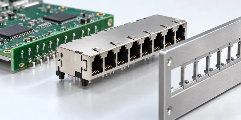
Mechanical inputs should be controlled in drawings and 3D models, not described only in email. Define the connector envelope, board-edge position, panel cutout, mating direction, latch access, cable exit, bend radius, keep-out zones, port pitch and allowable component height. Include the mating plug or module model so that interference is checked in the mated condition, not only around the empty receptacle.
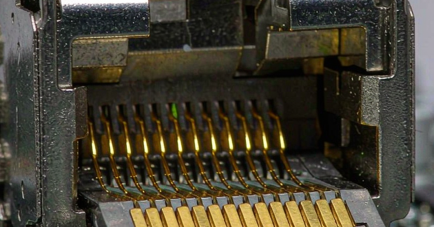
The PCB footprint deserves a separate review. Pad dimensions, drill sizes, annular rings, press-fit holes, mounting posts, shield tabs and solder-joint access must match the intended assembly process. Through-hole, SMT, press-fit and pin-in-paste structures impose different requirements on board thickness, hole tolerance, soldering profile, coplanarity and rework. A footprint copied from a visually similar connector is not a controlled source.
Reliable custom connector solutions also account for retention and service use. Specify expected mating cycles, insertion and withdrawal forces, vibration exposure and any latch, screw, board lock or chassis support. Check tolerance stack-up across the PCB, connector, enclosure and mating part at worst-case limits. Keying or polarization should prevent reversed installation without relying only on a printed mark.
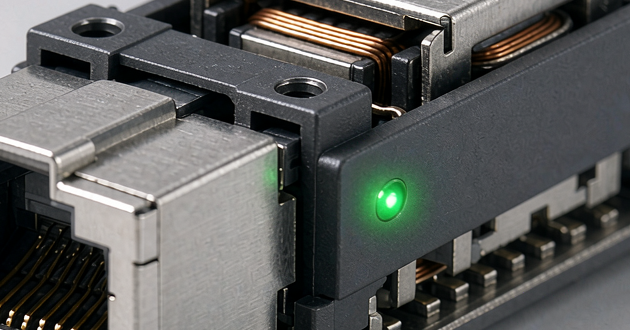
For networking equipment, front-panel design often links several details that must be reviewed together: port density, shield contact to the panel, LED visibility, light-pipe alignment, cage retention, heat-sink clearance and airflow. Approving each component in isolation can still produce an assembly that is difficult to mate, inspect or cool.
DFM and Tooling Checks Before Connector Prototyping
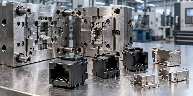
A design can meet electrical and mechanical targets and still be difficult to manufacture consistently. A formal DFM review should therefore occur before prototype tooling or production-intent tooling is authorized. The review should cover contact stamping, plating, plastic molding, metal forming, assembly sequence, tolerance capability, inspection access and the effect of the selected PCB mounting process.
Plastic parts need realistic wall thickness, draft, ribs, shutoffs and gate locations. Metal shields and cages need feasible bends, seams, spring features and panel-contact geometry. Contacts need manufacturable forming radii, retention features and plating definitions. Critical dimensions should be separated from cosmetic or nonfunctional dimensions so that the drawing does not impose unnecessary tolerances everywhere.
The tooling plan should state which sample characteristics will match production and which will not. A machined or 3D-printed housing may confirm fit, but it may not reproduce production dielectric properties, contact retention, surface finish or molded tolerances. Soft tools may support an early functional sample, while production tools are needed for meaningful capability and repeatability evaluation. The sample stage must be named clearly so that an appearance model is not approved as an electrical qualification sample.
Before tooling approval, confirm ownership and control of the following files: released 2D drawing, 3D model, PCB footprint, pin map, bill of materials, material and plating specifications, revision history, inspection criteria and approved deviations. The same revision must be used by design, tooling, sample assembly and test teams.
Sample Validation for Networking Hardware Connectors
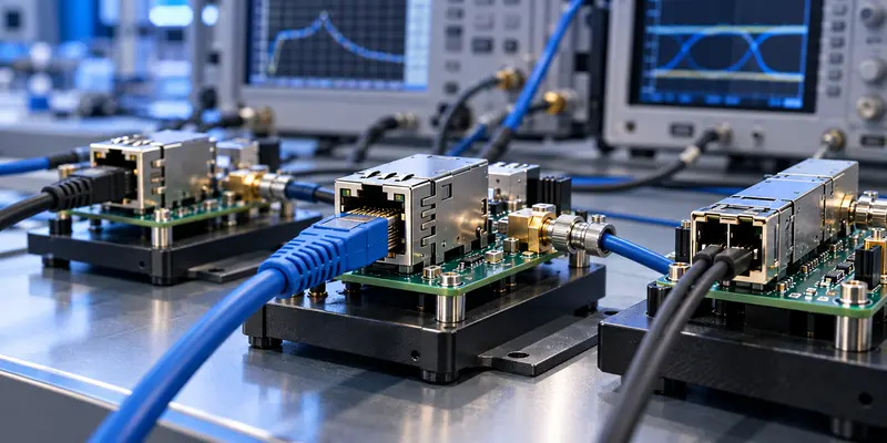
The first sample should answer pre-agreed engineering questions. A vague request to test whether the connector works usually produces an incomplete report. Build a sample validation matrix that links each requirement to a method, fixture, sample quantity, condition and acceptance criterion.
Begin with dimensional inspection and mating verification. Confirm critical dimensions, coplanarity, PCB fit, panel alignment, insertion and withdrawal behavior, retention and keying. Then verify continuity, contact resistance, insulation and any isolation or high-potential requirements appropriate to the interface. High-speed designs should be evaluated for the agreed signal-integrity metrics with the specified test board, launch and mating hardware. PoE or other powered ports need electrical and thermal checks under a defined current load, ambient condition and port-loading scenario.
Environmental and mechanical testing should reflect the real equipment. Temperature cycling, humidity, vibration, mechanical shock, durability, ESD or surge testing may be relevant, but the test list must be selected from application risk and applicable standards rather than copied from another product. Record preconditioning, mounting state and pass/fail limits so results are repeatable.
Validation should also include assembly observations. Check solderability or press-fit behavior, connector seating, shield-tab formation, inspection visibility, rework access and compatibility with production fixtures. A sample that passes bench measurements but requires manual adjustment at every assembly is not ready for scale-up.
Custom Engineering Support: Build a Complete RFQ Package
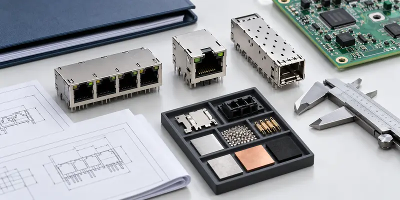
A useful RFQ gives the connector manufacturer enough information to identify conflicts before quotation and sampling. It should distinguish fixed requirements from preferences and open questions. Sending only a photo, target price and annual quantity may produce a fast quotation, but it does not establish a reliable engineering baseline.
Prepare one revision-controlled package containing:
- Application summary and target equipment, such as switch, gateway, NIC or industrial Ethernet controller.
- Connector family, mating counterpart and whether a standard, modified or full custom structure is expected.
- Protocol, data rate, pinout, impedance, power and PoE requirements.
- 2D drawing, 3D model, PCB footprint, panel opening and keep-out information.
- Mounting method, port configuration, shield, LED, light-pipe, heat-sink and retention requirements.
- Operating environment, mating cycles and relevant compliance or validation targets.
- Prototype quantity, forecast volume, project phase and required sample purpose.
- Validation matrix, report format and approval responsibility.
Ask the supplier to return a reviewed requirement summary with open items, proposed assumptions and drawing revision. This prevents a quotation from being mistaken for technical approval. GLGNET's custom connector design support includes product design, simulation, testing and in-house mold development capabilities. Projects can also be connected to GLGNET's networking connectivity solutions and connector product center to determine whether an existing platform can be modified before a new structure is developed.
Connector Prototyping FAQ for Networking Hardware
What information is needed for a custom connector?
Provide the application, mating interface, protocol and data rate, pin assignment, voltage and current, PoE requirement, PCB mounting method, footprint, mechanical envelope, panel opening, shielding, LEDs, operating environment and validation targets. Include drawings or models with revision numbers. Mark each item as fixed, preferred or open so the manufacturer knows which changes are acceptable during the engineering review.
When should a standard connector be customized?
Customize a standard platform when its basic interface is suitable but the equipment requires changes to port count, orientation, mounting, pinout, shielding, LED or light-pipe structure, retention or mechanical dimensions. A completely new design is better reserved for requirements that cannot be met safely by modifying an established platform. This decision should be made before PCB and enclosure geometry are frozen.
What should be checked before connector prototyping?
Check electrical ratings, data-rate targets, channel assumptions, pinout, grounding, PCB footprint, panel and enclosure fit, mounting process, tolerance stack-up, materials, plating, DFM status, tooling stage and the sample validation plan. Confirm that the supplier, PCB team and enclosure team are using the same drawing revision and mating-part model.
Should signal integrity validation happen before or after the first sample?
Both stages are useful for high-speed interfaces. Pre-prototype simulation can identify risks in contact geometry, pin assignment and PCB launch design before tooling. Physical samples are then needed to verify the manufactured connector and correlate the model with measurements. The test fixture, mating hardware and channel boundary should remain consistent so the two result sets can be compared meaningfully.
Custom Connector Solutions From GLGNET
GLGNET develops Ethernet and high-speed connector products for networking equipment, including magnetic RJ45, RJ45 jacks and SFP/QSFP-family connectors and cages. Its documented engineering resources cover mechanical design, mold-flow analysis, electrical engineering, signal-integrity simulation and testing, test-board design, mold development and laboratory validation.
For a project review, submit the intended data rate, PoE or power requirement, port layout, mounting type, pin assignment, shielding, LED or light-pipe needs, mechanical drawings and validation conditions. GLGNET can compare these requirements with existing magnetic RJ45 connector options, PCB-mounted RJ45 jacks, SFP cages and connectors or other available platforms before recommending a modified or custom route.
For related selection guidance, review the 2.5G vs 5G vs 10GBASE-T MagJack selection guide, the data center connector selection guide, the SFP port connector selection guide, and the Fast Ethernet vs Gigabit RJ45 guide for IP cameras and NVRs. Browse GLGNET’s magnetic RJ45 connector portfolio or explore networking connectivity solutions for more.