Choose data center connectors by defining the equipment-side port first: its protocol, aggregate data rate, number of electrical lanes, pluggable-module form factor, port density, PCB footprint, airflow and service requirements. For AI servers and network switches, SFP/SFP28, QSFP-family and OSFP systems solve different bandwidth and density problems. The host connector, cage, transceiver or cable, heat sink and board layout must be reviewed as one channel rather than selected independently.
For application-level product families and project support, review GLGNET’s data center connectivity solutions for AI servers, network switches and computing infrastructure.
Data Center Connectors Selection Starts With the Port Role
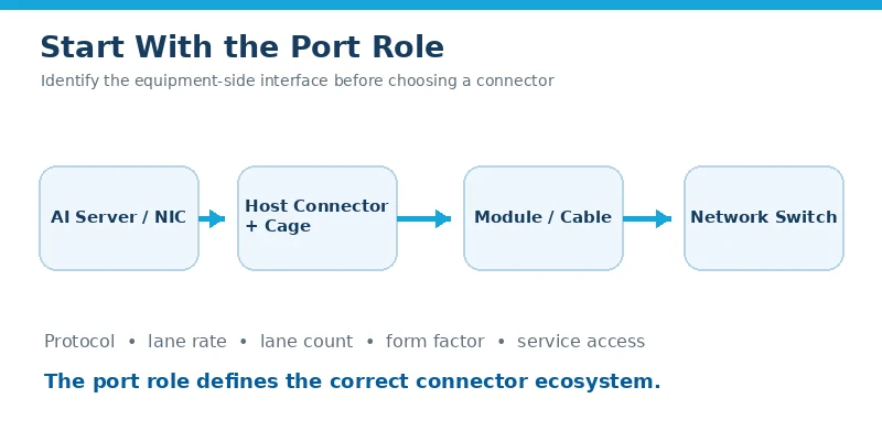
The phrase data center connectors can refer to several different interfaces. A fiber patch cord may terminate in LC, MPO/MTP or a very-small-form-factor connector. A rack link may use a direct attach copper cable, active electrical cable or active optical cable. Inside the network equipment, however, a pluggable port normally includes a host electrical connector on the PCB, a cage at the front panel, and a mating transceiver or cable module. These are related components, but they are not interchangeable terms.
Start by locating the connection in the system. A server network interface card may need a small number of adaptable ports, while a top-of-rack or spine switch may prioritize the highest practical front-panel bandwidth density. The same nominal network speed can therefore lead to a different form factor, cage arrangement, heat-sink design or port grouping. A connector chosen only from the aggregate speed can fit the protocol on paper and still fail the mechanical layout or thermal budget.
Define whether the port connects a server NIC to the network, connects switch tiers, or supports another equipment-side interface. Then identify the target protocol and module form factor required by the system architecture. Ethernet or InfiniBand speed names do not by themselves identify a host connector part number. The electrical lane rate and lane count, the applicable multi-source agreement, module type, PCB footprint and cage configuration must agree.
Data Center Connectors by Speed Lane Count and Form Factor
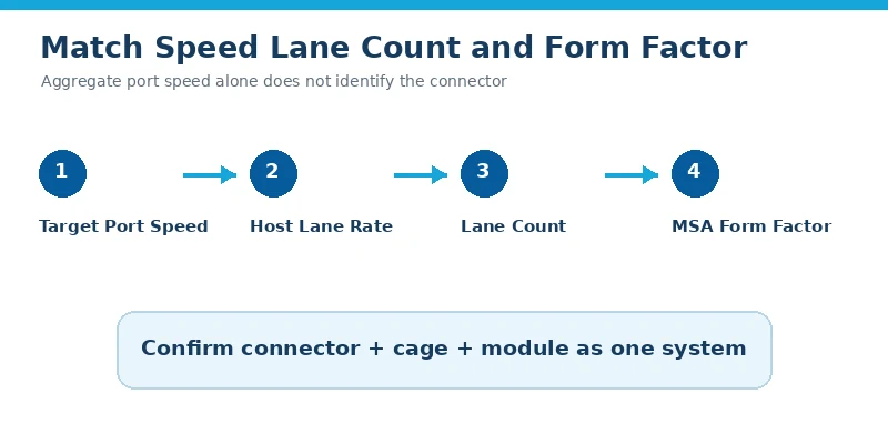
Aggregate port speed is the result of multiple electrical lanes and the signaling rate carried by each lane. That relationship matters because a 400G port, for example, may be implemented through different lane architectures and form factors. The connector system must match the host interface defined for the selected module and switch silicon design; it cannot be inferred from the “400G” label alone.
For a new design, record the required port speed and the actual host electrical interface separately. Confirm the MSA revision or system specification, the number of transmit and receive lanes, the modulation and lane rate expected by the board design, and whether backward compatibility is required. This prevents a common sourcing error: treating all modules with the same aggregate data rate as mechanically or electrically interchangeable.
The transmission medium is the next decision, but it applies to the complete link rather than the PCB connector alone. Very short equipment links may use passive direct attach copper where the channel budget permits. Longer or more difficult copper paths may require active conditioning, while optical modules and fiber are used when reach, isolation, routing or system architecture favors optics. Once that link is fixed, choose the host connector and cage specified for the corresponding pluggable form factor.
SFP QSFP and OSFP Data Center Connectors Compared
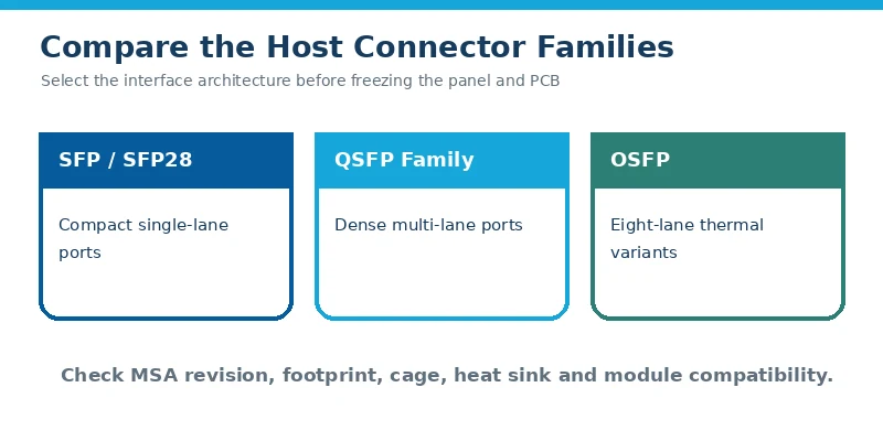
SFP-family data center connectors suit compact single-channel pluggable ports and remain useful for management, access, storage, server and lower-lane-count interfaces. SFP+ and SFP28 extend the family to higher lane rates while retaining a compact equipment-side format. They are a strong fit when flexible port count and familiar host-board integration matter more than maximum aggregate bandwidth per port.
QSFP connector systems use a multi-lane approach. QSFP, QSFP28 and QSFP-DD should not be treated as one undifferentiated product: their lane architecture, host connector, cage, thermal load and system application can differ. GLGNET’s QSFP product range includes connector and cage options with heat sinks, light pipes, EMI shielding and single or multi-port arrangements for data center and switching applications. The exact product must be matched to the module format and board design.
OSFP is also an eight-lane pluggable form factor. The OSFP MSA defines the mechanical module, card cage, electrical interface and pinout, and distinguishes thermal implementations such as an integrated heat sink or a riding heat sink. This makes OSFP relevant to dense, high-bandwidth switch platforms, but it does not make an OSFP module compatible with a QSFP-DD port. Choose between the families at the system-architecture stage, not after the front panel and PCB are fixed.
| Selection input | SFP SFP+ SFP28 | QSFP QSFP28 QSFP-DD | OSFP |
|---|---|---|---|
| Typical design priority | Compact, flexible single-channel ports | Higher aggregate bandwidth and dense multi-lane ports | High-bandwidth eight-lane ports with defined thermal variants |
| Best starting question | What single-lane host rate and module are required? | Which QSFP family, lane map and module format are required? | Which OSFP MSA variant and thermal implementation are required? |
| Mechanical checks | PCB footprint, cage, latch, panel opening | Connector/cage generation, ganged layout, panel pitch | Module/cage dimensions, heat-sink envelope, panel pitch |
| Thermal checks | Module power and local airflow | Heat sink, cage airflow and neighboring-port heating | Integrated or riding heat sink and chassis airflow |
| Do not assume | All SFP generations have identical electrical requirements | QSFP, QSFP28 and QSFP-DD are the same interface | OSFP and QSFP-DD modules are cross-compatible |
High Speed Connector Density PCB and Mechanical Requirements
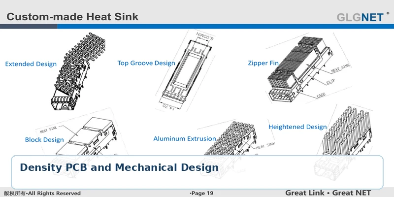
Front-panel density is not simply the number of cages that fit across a one-rack-unit opening. Port pitch affects airflow, heat-sink width, light-pipe routing, EMI spring contact, insertion and removal access, and the space available for PCB routing behind the connector. A dense arrangement can save panel area while increasing thermal coupling and channel-routing difficulty.
Build the mechanical stack from the mating module back to the PCB. Confirm the panel cutout, connector and cage datum, press-fit or other board attachment method, board thickness, keep-out zones, component height limits and heat-sink travel. For stacked or ganged cages, verify the exact port arrangement and light-pipe geometry rather than assuming that a similar-looking cage is a drop-in replacement.
Serviceability belongs in the same review. Operators must be able to insert and extract modules without interfering with adjacent ports or airflow components. LED indication must remain visible, and the heat-sink mechanism must maintain contact over the intended tolerance range. These requirements should be fixed before tooling or PCB release because changing a cage or panel geometry late can affect both the board and chassis.
Data Center Connectors for Signal Integrity EMI and Thermal Control

At high lane rates, the data center connector is one discontinuity in a complete channel that also includes package escape, PCB traces, vias, connector launch, module card edge and the selected cable or optical module. Connector performance should therefore be judged against a channel budget. Request insertion-loss, return-loss and crosstalk information for the relevant frequency range, but also review the recommended footprint and routing conditions used to obtain those results.
Preserve differential-pair geometry through the connector launch, minimize unnecessary stubs and via transitions, control reference-plane changes, and keep noisy power or clock structures away from high-speed lanes. The supplier footprint is a starting point, not permission to ignore the rest of the board. A connector with suitable standalone data can still underperform when the breakout, antipads, stack-up or return path differs from the evaluated configuration.
The cage and front panel form part of the EMI containment path. Check cage-to-panel contact, spring-finger engagement, seams, grounding strategy and the effect of adjacent ports. Light pipes and openings must be incorporated without creating avoidable leakage paths. EMC performance is system-dependent, so a catalog statement cannot replace chassis-level verification.
Thermal design is equally system-dependent. The heat generated by a pluggable module must move through the module case, heat sink and airflow path while neighboring components and recirculated air raise the local inlet temperature. Ask for the actual module power range, worst-case ambient, airflow direction and velocity, allowable case temperature, port population and fan-failure condition. Select a cage and heat-sink configuration only after those inputs are available.
Data Center Connectors Validation Before Production
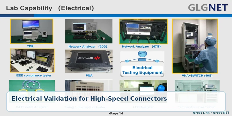
Validation should reproduce the intended host board, cage, module, airflow and chassis as closely as practical. Begin with dimensional inspection and mating checks, then verify contact and press-fit quality, retention, insertion and extraction behavior, and module engagement. For high speed connector channels, compare measured or simulated results with the system channel budget rather than relying on the connector name or aggregate port speed.
Electrical validation may include impedance, insertion loss, return loss and crosstalk over the required frequency range. Mechanical and environmental plans should reflect the project’s applicable specification and use conditions, including mating cycles, vibration or shock, temperature exposure and other reliability stresses where relevant. Thermal tests should use representative module power and port population. EMI testing should be performed in the intended enclosure because cage and panel interfaces materially affect the result.
Before approving a production part, freeze the connector and cage drawings, material and plating requirements, PCB footprint, press-fit or solder process, heat-sink and light-pipe configuration, packaging, inspection criteria and change-control expectations. Samples that fit a generic evaluation board are not enough; the final qualification must represent the customer’s own system.
GLGNET Data Center Connectivity Solutions for Product Selection
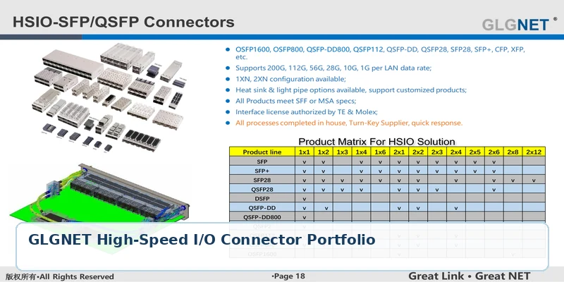
GLGNET supports equipment-side data center connectivity solutions for AI servers, switches and computing infrastructure. The verified online portfolio includes SFP, SFP+, SFP28 and QSFP-family connectors and cages, with applicable cage options such as heat sinks, light pipes, EMI shielding and multiple port configurations. GLGNET also describes engineering support for signal-integrity analysis, mechanical design, testing, sample validation and scalable manufacturing.
For an initial review, provide the equipment type, protocol, aggregate port speed, electrical lane rate and lane count, required module form factor, port map, panel and PCB drawings, board thickness, mounting method, module power, airflow conditions, EMI requirements and expected validation standard. These inputs allow the connector, cage and thermal configuration to be evaluated together instead of recommending a part from speed alone.
Explore GLGNET’s AI and data center connectivity solutions for the application-level portfolio, or review the QSFP connector and cage solutions for product configurations. If your project uses an SFP-family host interface, provide the target SFP, SFP+ or SFP28 form factor and board constraints so the electrical connector and cage can be reviewed against the intended NIC or switch design.
Data Center Connectors FAQ
What connectors are used in data centers?
Data centers use different connector layers: fiber connectors such as LC and MPO/MTP in cabling, copper or optical cable assemblies between equipment, host-side pluggable I/O systems such as SFP, QSFP and OSFP in servers and switches, plus separate power and cooling interfaces. Selection must begin with the connection location and function.
Which connector is used in AI servers?
There is no single AI server connector. The correct equipment-side connector depends on the NIC or accelerator architecture, protocol, lane rate, lane count, module form factor, port density and thermal design. SFP-family, QSFP-family and OSFP systems are common high-speed I/O choices for different port requirements.
How do QSFP-DD and OSFP differ?
Both are eight-lane pluggable form-factor families used for high-bandwidth equipment, but they have different mechanical and thermal ecosystems. They are not cross-compatible. The choice must follow the host architecture, MSA-defined interface, module availability, front-panel density and cooling plan.
Can a 400G or 800G speed label identify the correct connector?
No. Aggregate speed does not uniquely identify the lane architecture, host electrical interface or module form factor. Confirm the system specification, lane rate, lane count, connector footprint, cage and module before selecting a part.
What information should be sent for data center connector selection?
Send the equipment and port role, protocol, target speed, lane architecture, module form factor, port arrangement, PCB and panel drawings, mounting method, module power, airflow, EMI requirements, validation criteria and expected production volume. This is enough to begin a meaningful connector and cage review.
If your project also uses RJ45 MagJack interfaces, see the 2.5G vs 5G vs 10GBASE-T MagJack selection guide or the MagJack cross-reference guide for connector replacement and qualification support.