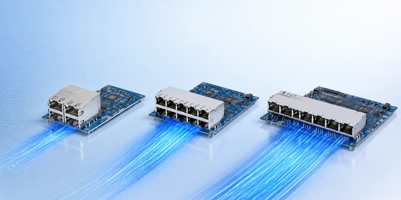
This guide explains why RJ45 plugs and female jacks use different termination arrangements, how to wire each end correctly, and what to check before connecting an access point or other Ethernet device.
Is T568B Wiring the Same for an RJ45 Plug and Female Jack?
T568B uses the same final pin assignment on both an RJ45 plug and a female jack. The physical wire positions may differ, but each conductor must still connect to its corresponding Ethernet contact.
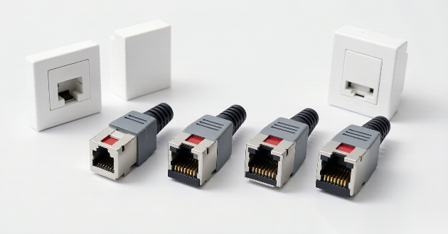
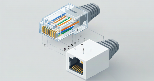
An RJ45 plug presents the conductors in the order of its eight front contacts. A female jack shows where the conductors enter its insulation displacement contacts, or IDC terminals.
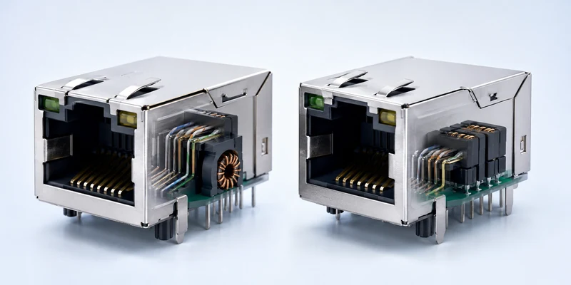
The IDC terminals are connected internally to the jack contacts. As a result, the orange pair may enter one section of the jack while the green or blue pair enters another, yet the front interface still follows the correct T568B pinout.
This was also the main point raised in the social media discussion. Several installers advised against comparing the back of the jack directly with the visible wire order inside the plug. Their recommendation was to use the wiring diagram supplied with the specific jack.
T568B defines the electrical relationship between the conductors and the eight RJ45 contacts. It does not require every connector to use the same internal structure or termination layout.
Why Does the RJ45 Female Jack Pinout Look Different?
The different appearance comes from the way each connector is designed and terminated.
An RJ45 plug has a narrow housing, so the eight conductors must enter in a single row. They are arranged directly in the sequence required by Pins 1 through 8.
The most confusing section is usually Pins 3 through 6. The blue pair occupies the two center contacts, Pins 4 and 5, while the green pair uses Pins 3 and 6. This creates the visible sequence:
White/Green – Blue – White/Blue – Green
In the social media discussion, one installer explained that the center two contacts form one pair and the contacts immediately outside them form another. This clarified why the green wires are separated in the plug rather than positioned next to each other.
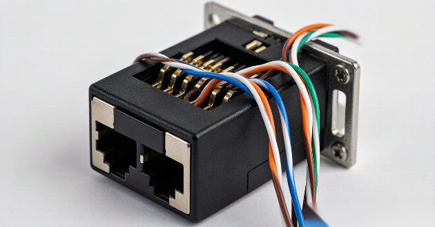
A female RJ45 jack has more space for cable management. Its IDC terminals can be positioned around the housing so that each twisted pair remains grouped during installation.
This arrangement helps the installer preserve the cable twists close to the termination point. It can also reduce unnecessary crossing between conductors and make punch-down installation easier.
The terminal layout is not universal. One jack may accept the cable from the rear, another may use side-entry IDC terminals, and a tool-free model may route the pairs through a termination cap.
Comments in the installation discussion also noted that different manufacturers often use different terminal arrangements. For this reason, a wiring layout from one jack should not be copied onto another model, even when both products support T568B.
When you are selecting the right component for a build, review how to choose the best RJ45 female connector for your network so the jack matches your cable category and termination style before you order.
How to Connect an RJ45 Plug to a T568B Female Jack
The plug and the jack should be terminated according to their own designs. They do not need to show the same visible color sequence.
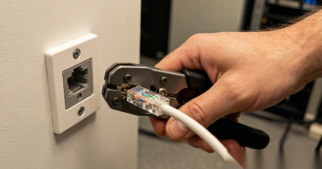
1. Terminate the RJ45 Plug in the Correct T568B Order
Arrange the eight conductors in the standard T568B sequence before inserting them into the plug.
Confirm the connector orientation before identifying Pin 1. Looking at the cable-entry side instead of the contact side can reverse the apparent order and lead to an incorrect termination.
The conductors should remain aligned as they enter the housing. Before crimping, confirm that each wire reaches the front of the plug and that the outer jacket is held by the strain-relief area.
2. Follow the T568B Color Code on the Female Jack
Locate the T568A and T568B diagram printed on the female jack. Use the B pattern and place each conductor into the matching IDC terminal.
Many jack labels use a full color block for the solid conductor and a partly white block for the striped conductor. Check each pair carefully:
White/Orange and Orange
White/Green and Green
White/Blue and Blue
White/Brown and Brown
A frequent recommendation in the social media comments was to “follow the B side” rather than rearrange the conductors to resemble the plug. That advice reflects how the jack is designed: its internal contacts already route each IDC position to the required Ethernet pin.
If the label is missing, damaged or difficult to interpret, check the manufacturer’s wiring diagram for that exact model. Using the layout from another jack can result in crossed conductors or split pairs.
3. Preserve the Twisted Pairs During Termination
Keep each pair twisted until it reaches the IDC area. Only separate enough conductor length to complete the termination.
Excessive untwisting can increase crosstalk and reduce signal performance. A basic continuity test may still pass, but the cable may become less reliable at Gigabit Ethernet speeds or over longer channel lengths.
The grouped terminal design of a female jack is intended to support pair management. The cable should follow that design rather than be reshaped to imitate the straight-line arrangement of a plug.
4. Test the Finished T568B Connection
Use a cable tester after both ends have been terminated.
A correctly wired straight-through link should show:
Pin 1 to Pin 1
Pin 2 to Pin 2
Pin 3 to Pin 3
Pin 4 to Pin 4
Pin 5 to Pin 5
Pin 6 to Pin 6
Pin 7 to Pin 7
Pin 8 to Pin 8
Testing was another recurring recommendation in the social media discussion. Because the jack’s internal routing cannot be confirmed visually, a wire-map test provides a more reliable result than comparing the two ends by appearance.
The tester should also be used to check for opens, shorts, reversals, crossed conductors and split pairs.
For a complete wiring reference before you start, read the RJ45 pinout guide for the full step-by-step T568B color sequence so every conductor lands in the correct IDC position.
Will a T568B Plug-to-Jack Connection Work with an Access Point?
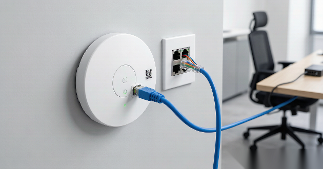
A correctly terminated T568B plug-to-jack cable can connect an access point, switch, router or other Ethernet device. The different terminal layouts do not affect network operation when all eight contacts are mapped correctly.
The first check is whether the female connector is actually designed for Ethernet. Some telephone jacks and other modular interfaces may resemble an RJ45 jack but use fewer contacts or a different pin assignment.
A suitable Ethernet female jack should normally include eight front contacts, eight termination points and a clear T568A/T568B wiring label. It should also be rated for the cable category being installed, such as Cat5e, Cat6 or Cat6A.
The cable and termination hardware must also be compatible. For example, horizontal Cat6 cable commonly uses solid conductors, while some modular plugs are intended for stranded patch cable. Conductor size, insulation diameter and cable outside diameter should be checked against the connector specifications.
If the connection is established but the link negotiates at only 100 Mbps, inspect all four pairs. Gigabit Ethernet requires all eight conductors, so one open or poorly terminated pair can prevent a Gigabit link.
The connected network device also matters. An access point can normally connect to a LAN port on a router, switch or modem-router gateway. A standalone modem may require a separate router before the access point can provide normal network access. This is a network configuration issue rather than a T568B wiring difference.
If you are planning a new deployment and weighing connector types, compare SFP vs RJ45 to decide which interface fits your switch and distance requirements before finalizing the bill of materials.
FAQ
1. Is T568B the same for an RJ45 plug and a female jack?
Yes. T568B assigns the same conductor to each RJ45 contact on both the plug and the female jack. The jack may use a different IDC layout, but its internal connections route the wires to the correct pins.
2. Why does a T568B female jack show a different color arrangement?
A T568B female jack groups the twisted pairs around its IDC terminals instead of displaying them in a straight Pin 1-to-Pin 8 sequence. This layout supports easier termination and helps preserve the pair twists near the contact points.
3. Should I copy the RJ45 plug wire order onto the female jack?
No. The RJ45 plug should follow the standard T568B contact order, while the female jack should follow the T568B diagram printed on that specific product. Copying the plug layout onto the jack can produce an incorrect wire map.
4. Can different RJ45 female jacks have different T568B layouts?
Yes. Manufacturers may use different IDC positions, cable-entry directions and internal routing designs. The physical layout can vary as long as the conductors are connected to the correct T568B contacts.
5. How can I confirm that a T568B plug-to-jack connection is correct?
Use a cable tester to verify that Pins 1 through 8 connect to the same numbered pins at the opposite end. The test should also confirm that the link has no opens, shorts, reversed conductors or split pairs.

Conclusion
T568B wiring remains the same for an RJ45 plug and a female jack, even though their physical wire arrangements may look different. The plug follows the standard Pin 1-to-Pin 8 sequence, while the female jack uses its own IDC layout to route each conductor to the correct contact.
For a reliable connection, follow the T568B order at the plug, use the B color label on the female jack, preserve the cable twists and test the finished link.
Need help selecting an RJ45 jack, magnetic RJ45 connector or custom pin configuration? If a finished link still will not reach Gigabit speed, follow the RJ45 troubleshooting checklist to find opens, split pairs or miswires, then contact GLGNET to discuss your Ethernet connection requirements.