RJ45 gold plating thickness is a purchasing specification only when it identifies the contact area, unit, acceptance limit and exact connector configuration. A quotation stating “gold-plated contacts” leaves those points unresolved. A quotation stating “30µin gold” still needs the applicable drawing, contact construction and evidence that the connector meets the intended service conditions.
For OEM buyers, the practical objective is to compare equivalent requirements and order a verifiable part. Start with the selected finish on the drawing, translate the units accurately, then connect the plating requirement to the mating environment and validation plan. The following approach uses an actual GLGNET MagJack drawing to show where a purchasing decision can go wrong.
Read the RJ45 Gold Plating Thickness Selected on the Drawing
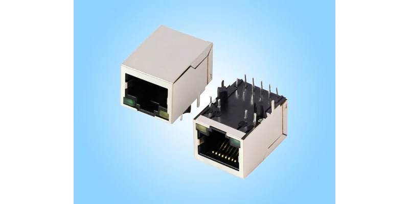
GLGNET’s JLFA1S805-G/YP magnetic RJ45 connector provides a useful example. Its linked customer drawing, file 130005-06811, contains a gold-plating option table listing GF, 3, 6, 15, 30 and 50 microinches. The filled selection box is beside 6µin. The material note separately specifies selected 6-microinch gold at the mating interface.
Those two details matter together. The table shows options represented in that drawing format; the filled box identifies the finish selected for this documented configuration. It does not prove that a 30µin version uses the same ordering code, is currently stocked, or has been approved against a particular customer test plan. Ask for the drawing and ordering code that will actually appear on the quotation and purchase order.
The location also matters. Gold at the mating interface describes the surface that meets the plug contact. It does not establish the same gold thickness over the complete contact, solder tails or shield. The drawing identifies phosphor bronze and nickel underplating in its material note. Treat the gold finish, underlying construction and solder-terminal finish as separate specification fields; confirm any unclear thickness or tolerance wording before releasing the BOM.
This is especially useful when comparing a magnetic RJ45 connector with an apparently equivalent alternative. The front opening may look identical while the selected finish and contact construction differ. Record the model, drawing revision, selected box and relevant material note on the comparison sheet, rather than relying on a family-level description or product photograph.
Read an RJ45 Contact Plating Specification in Microinches and Micrometres
A microinch and a micrometre are different units. 1µin = 0.0254µm, so the 6µin selection in the example equals 0.1524µm. Reading “6U” as 6µm would overstate that thickness by approximately 39.37 times. Where typography uses U, µ″ or another abbreviated notation, obtain written confirmation of the intended unit instead of assuming it from the number.
| Gold thickness in microinches | Equivalent in micrometres | Purchasing interpretation |
|---|---|---|
| 3µin | 0.0762µm | A numerical thickness; acceptance wording still required |
| 6µin | 0.1524µm | The selected option in this GLGNET drawing |
| 15µin | 0.3810µm | Not interchangeable with 15µm |
| 30µin | 0.7620µm | A thickness value, not a complete durability specification |
| 50µin | 1.2700µm | Requires the same contact-zone and acceptance checks |
These are unit conversions, not recommended grades for particular applications. GF, commonly used for gold flash, is a descriptive option unless its numerical requirement is defined in the controlling specification. Do not assign GF a universal thickness or interpret it as no gold. A supplier may define flash differently from another supplier, making a quotation comparison unreliable until both requirements are explicit.
An RJ45 contact plating specification should also state whether the figure is a minimum, a nominal target or a range. A measured average cannot automatically demonstrate compliance with a minimum at every required measurement location. Ask which contact surface is measured, how sampling works and how the result is evaluated against the drawing. This closes a more significant purchasing gap than adding extra decimal places to the conversion table.
Keep the original unit on the RFQ and place the converted value beside it for reference. This gives engineering, purchasing and incoming inspection a common reading while avoiding accidental changes caused by rounding. If the supplier proposes an alternative finish, obtain a revised specification rather than changing the unit label on an existing drawing.
Match the RJ45 Jack Connector Contact System to Operating Conditions
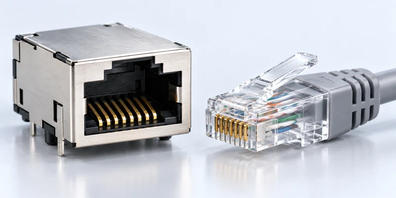
The useful question is how the complete RJ45 jack connector will maintain an acceptable connection in service. Gold thickness contributes to that result, but contact geometry, normal force, wiping action, base material, underplating and the mating plug also influence the contact system. A thicker finish cannot compensate automatically for an unsuitable mechanical design or an uncontrolled mating interface.
Samtec’s technical discussion of contact force and mating cycles explains why cycle capability depends on several variables. Its examples relate to its own contact systems; they are not cycle ratings for a GLGNET RJ45 MagJack. Use this distinction when a supplier offers a generic plating chart as proof of durability. Request evidence for the proposed contact design and finish, with the tested counterpart and acceptance criteria identified.
Describe use in concrete terms. A fixed controller connected during installation has different handling requirements from a service interface unplugged during every maintenance visit. Include expected mating operations during production testing, installation, troubleshooting and field service. State whether ports spend long periods unmated, whether dust or process vapours can reach the contact area, and whether vibration or temperature cycling is part of the installed environment.
For a PoE application, provide the power requirements and expected connection or disconnection conditions separately. Gold thickness alone does not qualify an RJ45 connector for PoE, establish current capacity or determine Ethernet speed. A supplier needs to match the complete model and its electrical and environmental requirements. The selected 6µin drawing discussed here should not be treated as permission to use that model in an unspecified powered application.
Record any proposed lubricant, cleaning process or change in mating-plug finish for engineering review. Do not introduce these as informal production fixes: they change the contact system being evaluated and may require additional compatibility or process evidence.
Compare RJ45 Connector Gold Plating Options Against Verified Durability
Comparing RJ45 connector gold plating options becomes useful when the rest of the requirement stays visible. Samtec’s overview of gold thickness selection describes the trade-off between application needs and plating cost, while stressing that thickness is not the sole determinant of performance. It provides a reason to ask better questions, rather than a universal thickness threshold for RJ45 products.
For a fixed indoor installation, establish the actual connection count, atmosphere and required electrical performance before paying for an unneeded finish change. For a frequently serviced product, request the required mating-cycle test sequence and the electrical checks after cycling. For equipment exposed to humidity or corrosive contaminants, identify the relevant exposure and acceptance criteria. Merely increasing the gold figure does not define the environmental test the finished connector must pass.
Compare the evidence as carefully as the headline number. Does the test identify the exact model or a justified representative construction? Was the same finish tested? Which plug was used? Were measurements made before and after conditioning? Does the report state contact-resistance limits and any observed failures? A report for a different contact system should be explained, rather than silently accepted as equivalent.
Distinguish design qualification from delivery inspection. A qualification report may demonstrate performance under a defined sequence; a lot inspection record addresses the supplied material and sampling agreed for production. One does not automatically replace the other. Neither a brochure claim nor a photograph of test equipment proves that a particular shipment met the purchase specification.
Ask suppliers to quote the same defined contact zone, acceptance requirement and documentation scope. If an alternative finish changes qualification, inspection availability, minimum order quantity or lead time, have those differences stated separately. Obtain current figures directly; there is no defensible universal percentage saving from changing 30µin to 6µin across different RJ45 constructions.
Consider two quotations: one identifies a 6µin minimum on a controlled mating area, while another simply lists “gold flash.” The first describes a measurable requirement; the second still needs clarification. This does not establish which connector is more suitable, but it explains why their prices cannot yet be compared on plating alone. Ask both suppliers to respond to the same requirement, and document any exception before selecting the commercial offer.
Give the RJ45 Connector Supplier a Verifiable Plating Requirement
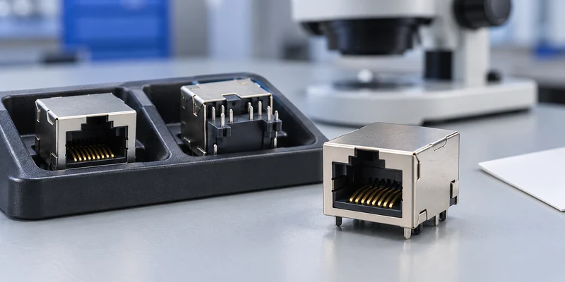
Before sending an RFQ to an RJ45 connector supplier, turn the engineering choice into a requirement that can survive quotation, sample approval and production handover. The following fields belong in the agreed specification, with unresolved values clearly assigned for confirmation.
| RFQ or approval field | What engineering and purchasing should agree |
|---|---|
| Part identity | Complete ordering code, drawing number, revision and selected finish |
| Contact region | Defined mating area; solder-tail and shield finishes recorded separately |
| Thickness requirement | Unit, minimum/nominal/range, tolerance and applicable reference |
| Contact construction | Base material, underplate and any controlled finish details |
| Inspection evidence | Measurement method, location, sampling, acceptance and traceability |
| Service validation | Mating counterpart, cycles, environmental sequence and electrical limits |
| Change control | Approval needed before changing finish, construction or ordering code |
For thickness inspection, ask whether the proposed method can measure the specified contact zone and layer system. Fischer’s XRF measurement guidance describes X-ray fluorescence as a non-destructive method for determining coating thickness and composition. Instrument choice, measuring spot and calibration matter. Request a report that identifies the sample, location, unit and result, together with the method and acceptance basis; a standalone number without these details is difficult to audit.
GLGNET’s company profile identifies a plating thickness tester in its mechanical laboratory equipment section on page 16. That is relevant background when discussing inspection support. It does not establish that every model or batch receives a particular test, or that a particular report format is automatically supplied. Confirm the available evidence and agreed inspection scope for the exact order.
For incoming inspection, define how a discrepancy will be resolved before parts arrive. If the drawing specifies a minimum and the report lists an average, ask for the underlying readings and agreed evaluation method. If buyer and supplier results differ, compare the measurement location, preparation, calibration and layer model before rejecting or accepting the lot. A colour photograph can document appearance, but cannot establish the thickness of the gold layer.
After sampling, retain the approved drawing and sample identity with the BOM record. A subsequent quotation using a shortened part number should be reconciled before purchase. For broader supplier qualification questions, use the OEM connector sourcing checklist alongside this plating-specific review.
To compare a finish for your project, send GLGNET your existing drawing, expected mating operations, operating environment and required inspection documents. Request model-specific plating options and available verification information before comparing quotations. The magnetic RJ45 range is a starting point for product matching; the approved configuration and evidence define what purchasing should order.
RJ45 Gold Plating Thickness FAQs
Is 30µin gold plating always necessary for an RJ45 connector?
No universal requirement follows from the thickness alone. The appropriate finish depends on the applicable product specification, contact system, mating requirements and environment. A customer or application specification may require 30µin; follow that requirement or obtain formal approval for an alternative. Do not replace it using a general article’s recommendation.
Does a thicker gold layer guarantee more mating cycles?
No. The contact design, mating counterpart, force, wear conditions and environment also affect durability. Confirm a cycle rating using evidence for the proposed construction and defined acceptance criteria, rather than converting gold thickness directly into a service-life promise.
Does a plating option table mean every option is stocked or approved?
No. The selected option identifies the documented configuration. Other entries need confirmation of the exact ordering code, current availability, applicable drawing and validation status. Keep those confirmations with the approved BOM and purchasing record.
For related connector guidance, review the ganged vs. stacked magnetic RJ45 layout guide, the RJ45 LED connector troubleshooting guide, the 2.5G vs 5G vs 10GBASE-T MagJack selection guide, the PoE magnetic RJ45 connector guide, and the custom connector design checklist. Browse GLGNET’s magnetic RJ45 connector portfolio or explore networking connectivity solutions for more.