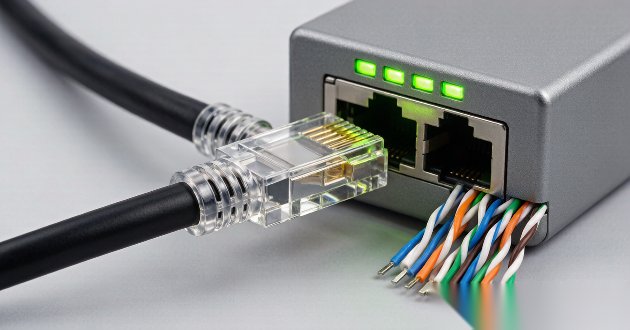
Choose a PoE magnetic RJ45 connector by matching it to the Ethernet PHY, the camera or NVR port role, the required PoE type, worst-case current and temperature, shielding strategy, PCB footprint, and manufacturing process. A connector that fits the panel is not automatically electrically compatible. The final choice should be verified with the connector datasheet, PHY reference design, PoE controller architecture, and system qualification tests.
What Is a PoE Magnetic RJ45 Connector for an IP Camera or NVR?
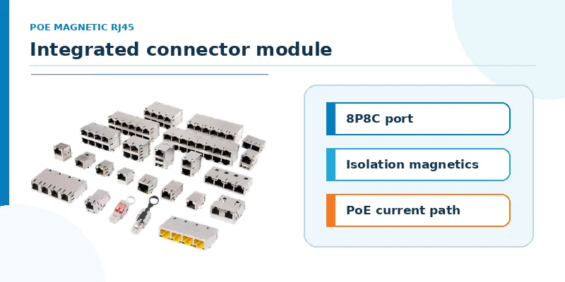
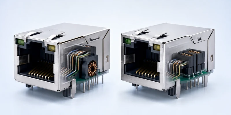
A PoE magnetic RJ45 connector—also called an RJ45 MagJack, integrated connector module, or RJ45 with integrated magnetics—combines the 8P8C modular interface with Ethernet isolation transformers and, depending on the design, common-mode chokes, termination elements, LEDs, and shielding. Integration reduces the number of separate magnetic components on the PCB and can simplify routing around the network port.
The term does not mean that the connector is a complete PoE power supply. In an IP camera, the port is normally part of a powered-device (PD) design that includes a PoE PD controller, rectification and protection, and downstream power conversion. A PoE NVR or surveillance switch with powered ports operates on the power-sourcing-equipment (PSE) side and requires its own PSE controller, power path, protection, and total power budget. The magnetic Ethernet connector must be suitable for the relevant side of that architecture, but it cannot replace those circuits.
For a broader view of where these interfaces sit in camera, recorder, and access-control hardware, see GLGNET’s security Ethernet connector solutions for IP cameras and NVRs.
Does It Matter What RJ45 Connector You Use for a PoE Camera?
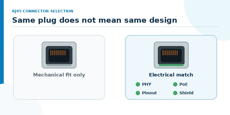
Yes. Two RJ45 jacks may accept the same plug and still differ in magnetic topology, supported data rate, PoE current path, pin assignment, footprint, shield design, LED circuit, operating range, and soldering method. A standard RJ45 jack used with discrete magnetics may be correct for one camera design, while an integrated magnetics RJ45 may be the better choice when board area and assembly simplicity matter. Neither should be selected from the mechanical envelope alone.
The first distinction is the port role. The camera receives power and data as a PD. A PoE-enabled NVR port or switch port supplies power as a PSE, while an NVR uplink may carry data only. Those ports can use physically similar connectors but require different center-tap access, magnetic circuits, and surrounding power electronics. When qualifying a second source, compare the internal schematic and complete pinout—not only the front opening and pin pitch.
The second distinction is the product environment. A connector inside an outdoor camera enclosure may face higher internal temperature, condensation risk, electrical transients, and a mechanically constrained cable entry. A multi-port NVR has a different problem: many energized ports share limited front-panel and PCB space, so current, copper loss, shield termination, and heat concentration must be reviewed across the port bank.
Choose a Magnetic RJ45 Connector by Camera Bandwidth and PHY
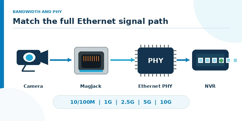
Start with the Ethernet PHY rather than the camera’s marketing resolution. Video bitrate depends on codec, frame rate, image complexity, analytics, and stream settings; a higher-megapixel label alone does not prove that a 10G port is required. The connector magnetics must support the PHY interface and the specified Ethernet rate, while the wider network must handle the combined traffic.
For a single camera, 10/100BASE-T or 1000BASE-T may be sufficient depending on the actual device architecture. A 1000BASE-T RJ45 interface uses all four twisted pairs for data, so the magnetic circuit must provide the required four data channels. A two-pair 10/100 magnetic module is not a substitute. At the NVR, aggregation changes the calculation: even if each camera link is modest, the NVR uplink or a dense switch may require more bandwidth because it carries multiple simultaneous streams.
PHY compatibility is more specific than a speed label. Review the PHY vendor’s transformer requirements, turns ratio, inductance, insertion loss, return loss, common-mode performance, isolation requirement, center-tap arrangement, and recommended termination. Then compare the candidate connector’s internal schematic and pinout. There is no universal PCB footprint for every magnetic RJ45 connector, and LED pins or center taps can move between families.
Match PoE Magnetics RJ45 Power to the Camera Load
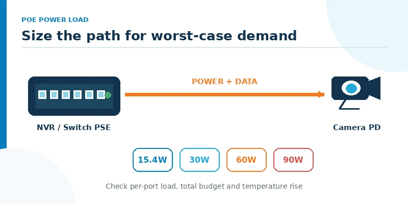
Power selection begins with the camera’s worst-case input, not its typical daytime consumption. Include infrared LEDs, heaters, wipers, pan-tilt-zoom motors, local storage, startup, and accessories that may operate together. On a PSE NVR or switch, verify both the maximum allowed per port and the total budget available when multiple cameras enter a high-load state at the same time.
| PoE type | Pairs used for power | Maximum PSE output | Selection implication |
|---|---|---|---|
| Type 1 — IEEE 802.3af | 2 pairs | 15.4 W | Confirm the PD’s delivered-power need after cable loss. |
| Type 2 — IEEE 802.3at | 2 pairs | 30 W | Common for cameras with additional functions; qualify current and heat. |
| Type 3 — IEEE 802.3bt | 2 or 4 pairs | Up to 60 W | Confirm pairset topology, current balance and simultaneous load. |
| Type 4 — IEEE 802.3bt | 4 pairs | Up to 90 W | Requires four-pair power-path and thermal qualification. |
Use RJ45 With Integrated Magnetics for Isolation and EMI Control
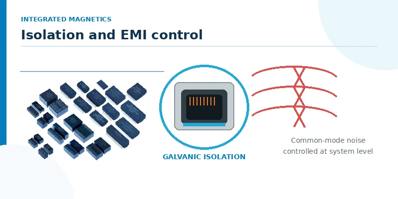
Ethernet magnetics provide galvanic isolation and help control common-mode noise between the PHY and the cable. Integration can shorten exposed routing and reduce component count, but EMC performance still depends on the full design: PHY layout, pair symmetry, termination, shield-to-chassis path, return-current control, protection placement, cable, panel construction, and enclosure grounding.
For an outdoor camera or electrically noisy installation, a shielded RJ45 with magnetics may be appropriate, but a metal shell alone does not create an outdoor-rated port or guarantee EMC compliance. Ingress protection comes from the complete enclosure, gasket or gland, mating interface, and assembly. Surge and ESD protection are normally coordinated at the system level; an ICM should not be described as a replacement for external protection unless the specific part documentation explicitly includes that function.
Ask for signal-integrity and isolation data at the required speed, and review the shield tabs, panel contact, chassis-ground concept, and spacing around the connector. Then test the assembled camera or NVR with its production cable and enclosure. This turns “shielded” from a catalog checkbox into a verifiable design decision.
Select a PCB Mount Magnetic RJ45 Connector for Camera and NVR Hardware
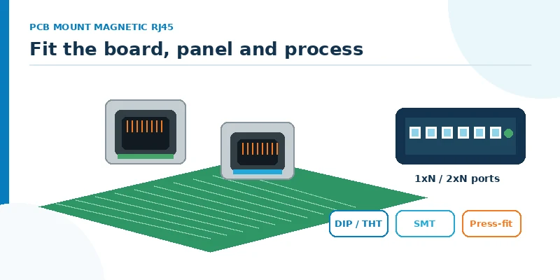
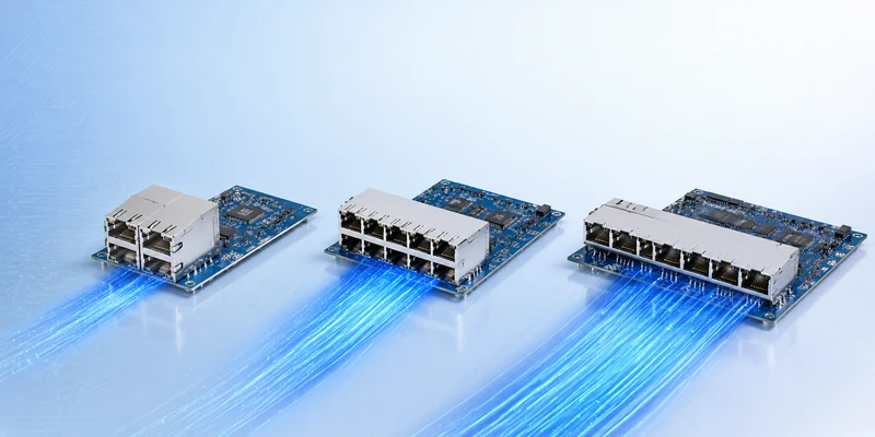
Mechanical selection must be performed against the PCB and enclosure together. A compact camera commonly uses a single-port right-angle or vertical magnetic RJ45, while an NVR may use 1×N ganged or 2×N stacked ports. Check board-edge position, connector height and depth, latch orientation, panel cutout, cable-release access, keep-out zones, and clearance for adjacent components. Integrated LEDs reduce external parts but add pin and circuit requirements that must match the board.
Mounting and assembly also matter. Through-hole/DIP pins can provide robust board retention; SMT can support automated surface-mount processing in an appropriate design; press-fit may be useful in some dense assemblies. The choice depends on the connector family, board thickness, production line, soldering profile, repair strategy, and mechanical load. Confirm whether the model is intended for wave soldering, reflow, pin-in-paste, or press-fit before the footprint is released.
GLGNET lists single- and multi-port magnetic RJ45 configurations, several orientations, LED options, and DIP, SMT, or press-fit mounting across its portfolio. Availability and electrical ratings are model-dependent; review the magnetic RJ45 connector options and request the exact drawing and datasheet for the shortlisted part.
Validate a PoE Magnetic RJ45 Connector for 24/7 Security Equipment
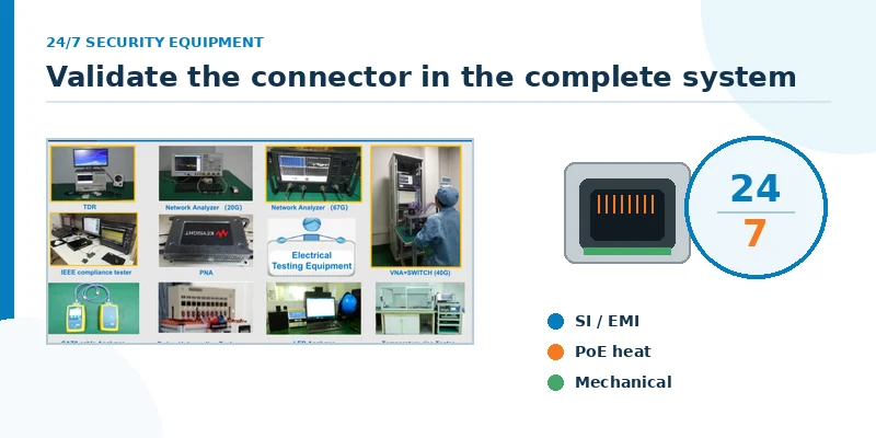
A datasheet comparison is necessary but not sufficient for surveillance hardware expected to operate continuously. Qualification should reproduce the worst electrical, thermal, mechanical, and manufacturing conditions that the complete product will see. For cameras, that may mean maximum ambient temperature with IR illumination and heaters active. For an NVR, it may mean all PoE ports sourcing their planned load while the processor, storage, and power supply are also hot.
Begin with a schematic review that checks the PHY-side and cable-side connections, center taps, terminations, LEDs, shield, chassis ground, and PoE controller interface. Follow with signal testing at the target Ethernet rate, PoE load and temperature-rise measurements, and EMC, surge, ESD, isolation, environmental, and mechanical tests required by the product. Use production-intent PCB material, cable, enclosure, solder process, and power components where possible.
Second-source qualification should repeat the critical tests. “Pin compatible” must mean that the footprint, internal schematic, electrical parameters, materials, solder process, panel fit, and compliance evidence are acceptable—not simply that the replacement can be inserted into the same holes. A controlled pilot build can expose LED polarity, shield contact, solderability, and tolerance-stack issues before volume production.
PoE Magnetic RJ45 Connector Selection Checklist
A useful RFQ gives the supplier enough information to evaluate the port as part of a system. At minimum, provide the application and port role, Ethernet PHY and data rate, PoE type and worst-case load, internal magnetic schematic or reference part, required orientation and port count, PCB footprint constraints, LED and shield requirements, mounting/solder process, operating environment, compliance targets, expected volume, and validation needs.
Do not accept a recommendation based only on “Gigabit PoE RJ45.” Request a model-specific datasheet and drawing, then close the following four gates before release:
Electrical: PHY topology, speed, isolation, insertion/return loss, common-mode behavior, PoE current path, resistance and pinout.
Thermal and environmental: actual simultaneous load, enclosure ambient, temperature rise, humidity/condensation, vibration and material limits.
Mechanical and manufacturing: footprint, panel opening, latch access, LEDs, shield contacts, board retention, soldering or press-fit process.
Evidence: qualification reports, compliance documentation, change-control expectations, sample plan and second-source comparison.
PoE Magnetic RJ45 FAQ
What type of Ethernet cable is best for connecting a PoE camera?
Use a standards-compliant balanced twisted-pair cable category that supports the Ethernet rate, PoE type, channel length, installation environment, and local code. Cat5e can support many 1000BASE-T camera links, while Cat6 or Cat6A may offer additional margin or be specified for higher rates and installation conditions. For high-power PoE, conductor size, bundle heating, temperature rating, connector compatibility, and installation quality also matter. See GLGNET’s guide to RJ45 wiring for PoE for the cable-side design issues.
Which PoE switch is best for IP cameras?
Choose a standards-based switch whose per-port PoE type covers the highest-load camera and whose total PoE budget covers the planned simultaneous load with appropriate design margin. Also check port count, uplink bandwidth, managed features, environmental rating, redundancy, and whether the NVR has built-in PSE ports. This is a system decision; the switch rating does not remove the need to qualify the connector and power path inside the NVR or camera.
Which RJ45 pins are used for PoE?
The answer depends on the Ethernet and PoE mode. Two-pair PoE uses two pairsets, while four-pair PoE uses all four pairsets. In 10/100BASE-T, Mode A can apply power over the data pairs and Mode B over the spare pairs; 1000BASE-T uses all four pairs for data and superimposes power through the transformer center taps. Follow the IEEE-compliant PSE/PD design and the exact connector schematic rather than wiring power to pins from a generic diagram.
Is a standard RJ45 jack the same as a magnetic RJ45 connector?
No. A standard jack is primarily the modular interface and requires separate Ethernet magnetics in the system. A magnetic RJ45 connector integrates the transformer and often other magnetic or indication features. Either architecture can be valid when correctly designed. The choice depends on PCB space, routing, sourcing, serviceability, EMC strategy, cost, and the PHY/PoE circuit.
Can a shielded MagJack make an outdoor camera port waterproof?
No. The shield helps with chassis bonding and electromagnetic control; it does not by itself establish an ingress-protection rating. Waterproofing depends on the complete enclosure, gasket or gland, mating connector, cable entry, assembly process, and validated IP rating.
Choose a PoE Magnetic RJ45 Connector With GLGNET
GLGNET’s company materials describe magnetic RJ45 (ICM) families spanning 10/100M through 10G, multiple port layouts and orientations, LED options, and DIP, SMT, or press-fit mounting. PoE levels up to 150 W are listed within the portfolio, but every speed, PoE level, pinout, mounting process, and environmental rating must be confirmed for the specific model. GLGNET also documents mechanical, electrical, signal-integrity, simulation, testing, and analysis capabilities for connector development and qualification support.
To obtain a defensible recommendation, send your PHY, PoE, PCB, enclosure, and validation requirements to GLGNET. A drawing, reference part number, target data rate, PSE/PD role, maximum load, port arrangement, shield/LED needs, and manufacturing process will allow the engineering team to compare model-specific options efficiently.
For other RJ45 magnetics decisions, also review the 2.5G vs 5G vs 10GBASE-T MagJack selection guide, the MagJack cross-reference guide, and the data center connector selection guide for AI servers and network switches. For industrial switch and gateway ports, see the industrial Ethernet connector guide. Browse GLGNET's magnetic RJ45 connector portfolio or explore networking connectivity solutions for more.