A PoE MagJack power rating is useful only when its location and conditions are clear. A 90W IEEE PoE source rating, a 120W connector description and a manufacturer's 150W portfolio statement describe different things. They do not establish that the same amount of power reaches the powered device, or that every connector in the range supports the highest number.
For OEM engineering and purchasing teams, the task is to compare a defined interface and current path. Start with the power the equipment needs, identify the applicable PSE and PD requirements, then check the exact connector drawing and rating conditions. The following guide uses GLGNET's published material to turn those distinctions into a practical supplier comparison.
Identify Where a PoE MagJack Power Rating Applies
Power sourcing equipment, or PSE, supplies the Ethernet link; the powered device, or PD, receives power at the other end. The values at their respective interfaces differ because the channel has losses. The power available to the equipment after its DC/DC conversion is a further system-level calculation, dependent on the actual conversion and operating conditions.
The Ethernet Alliance's explanation of IEEE PoE conformance identifies up to 90W at the PSE and 71.3W at the PD for the IEEE 802.3bt capability discussed there, using four wire pairs. Therefore, a PD requirement of 90W is not satisfied merely by choosing a standard 90W PSE port and a connector carrying a larger wattage label.
| Rating location | What the number describes | What purchasing must confirm |
|---|---|---|
| PSE interface | Power supplied into the channel under the specified PoE implementation | Supported class, allocation and operating conditions |
| PD interface | Power available at the receiving interface under the applicable conditions | Required PD power and the class the system can negotiate |
| Connector or magnetic assembly | A supplier's component capability statement | Current paths, voltage, temperature and rating definition |
| Equipment load | Power needed after conversion and distribution | Conversion losses, startup behaviour and actual load demand |
A component rating does not perform classification or allocate power. Those functions belong to the PSE/PD implementation. Nor does using a compliant controller alone qualify the complete equipment: the connector, magnetic circuit, PCB, protection and remaining system implementation still require evaluation.
Write the required power location into the RFQ. “Equipment needs 70W at the PD input” is a different requirement from “equipment load needs 70W after conversion.” Leaving that location undefined can produce technically different proposals that appear comparable only because both quotations contain the same wattage.
Read High Power Magnetic RJ45 Labels: 90W, 120W and 150W
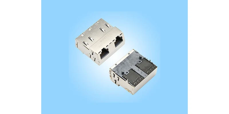
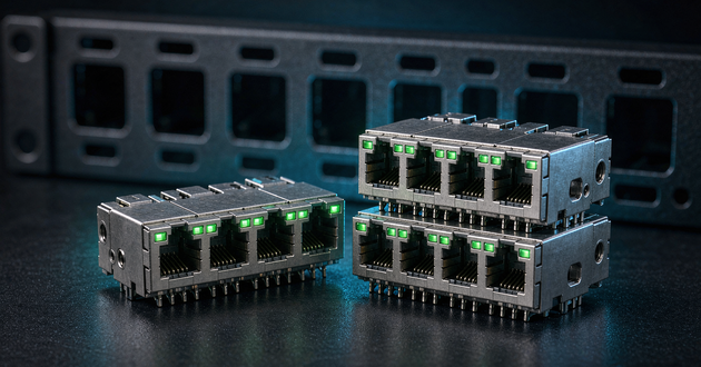
GLGNET's JGRPG2T1034PW product page lists a 1×2, 10GBASE-T, through-hole assembly with 120W four-pair PoE. Its linked PDF file 130067-00111 contains a 4PPoE(120W) description. However, the drawing title identifies JGRBPG2T1034PW, with an additional B. Confirm the full ordering code and applicable drawing before applying those specifications to a purchase.
This is a useful high power magnetic RJ45 example because it exposes the next purchasing questions. Does the stated power apply to each port or the complete assembly? Which current-carrying paths and voltage define it? Which operating conditions accompany the rating? A short component description does not resolve all of these points by itself.
GLGNET's company profile, page 20, describes its Magnetic RJ45 portfolio with PoE capability up to 150W. That is portfolio information, not a controlled specification for an identified 150W SKU. It should prompt a request for the appropriate part and supporting data rather than a promise that the illustrated 120W configuration delivers 150W to a PD.
There are also non-standard system implementations above the familiar IEEE power levels. Texas Instruments' TIDA-050026-23881 reference design explicitly separates up to 90W per port for IEEE 802.3bt applications from up to 120W for non-standard applications. This is evidence that the implementation must be identified; it is not evidence that a GLGNET component, or any unspecified counterpart, qualifies that TI system.
Read the three labels accordingly: 90W can identify the defined IEEE PSE capability; 120W here identifies a published component description requiring its conditions; 150W here identifies a product-family statement requiring a specific configuration. None should be substituted for the required PD power or end-equipment qualification.
Compare PoE RJ45 Connectors by Current Path and Magnetic Circuit
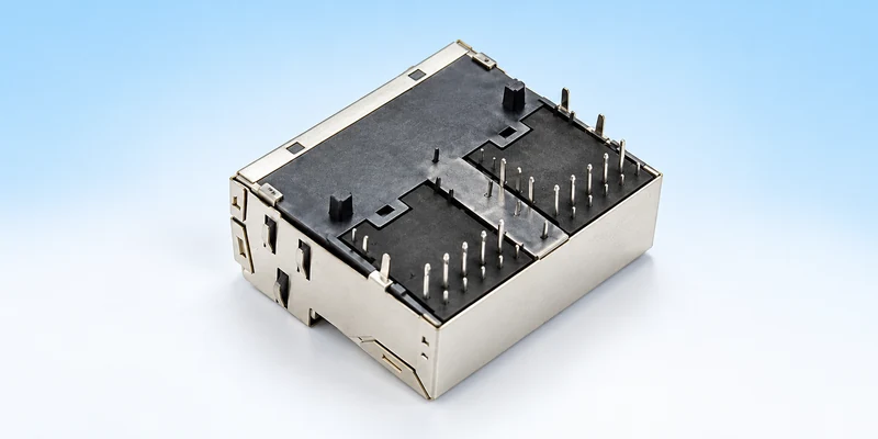
For PoE RJ45 connectors, the current route is more informative than a wattage comparison alone. Determine whether the OEM port is a PSE or PD, which pairsets carry power, where the magnetic centre taps connect and how the power reaches the relevant controller or rectification circuit. Confirm those connections against the Ethernet PHY requirements and the proposed connector schematic.
On page 2 of file 130067-00111, the DC current/voltage field for the PSE pins states 1.15A maximum at 57VDC, continuous. The schematic separately identifies PSE1/2, PSE3/6, PSE4/5 and PSE7/8 connections. Retain that PSE-pin designation when discussing the value. Do not silently restate it as a universal 1.15A rating for each of the eight cable contacts, or multiply it by a convenient contact count to manufacture a delivered-power claim.
Keep signal measurements separate from power-path ratings. The same document gives an OCL condition of 120µH minimum at 100kHz and 100mV, with 19mA DC bias. That bias belongs to the inductance test. It is not the PoE load current. Likewise, the listed isolation test is a withstand-test condition, not the voltage permitted for continuous power delivery.
When comparing two candidates, map each supplier's current notation onto its actual circuit. “Per contact,” “per pair,” “per pairset” and a named PCB power pin can refer to different conductors or combinations. Ask the supplier to identify the applicable terminals and current distribution on the schematic. Do not assume that current divides equally across all physical contacts under every condition.
Ethernet compatibility remains a separate requirement. The headline power value does not establish the required turns ratio, insertion loss, return loss, common-mode performance or PHY-side connections. Keep the relevant magnetic limits and their frequency, bias and temperature conditions attached to the proposed part, even when the mechanical fit and power description appear suitable.
Check the RJ45 MagJack Thermal and Electrical Rating Conditions
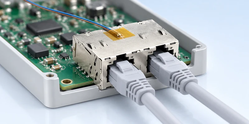
A current rating for an RJ45 MagJack needs the conditions under which it applies. Ask for the reference ambient or measurement location, allowed temperature rise, port-loading pattern, enclosure conditions and any applicable derating. If those details are absent, mark them as unresolved rather than assuming that the maximum operating temperature permits maximum current in every installation.
The public 130067-00111 drawing lists operation from −40°C to +85°C. This range does not, by itself, provide a current-versus-temperature curve or prove simultaneous maximum loading of both ports in an enclosed product. Request the relevant current and thermal evidence for the proposed configuration and installed conditions.
Describe the test arrangement sufficiently for engineering to interpret it. A connector tested on an open board can encounter a different local environment when installed beside PHYs and regulators behind a panel. The combination of active ports, enclosure orientation and airflow matters. Specify the required operating combination and retain the measured locations with the results; a single unqualified maximum-temperature figure provides little basis for comparing suppliers.
Electrical checks should use the required data activity and power arrangement together. Review the intended startup behaviour, allocated power, steady operation and relevant fault conditions with the system engineering team. An illuminated link LED or a load operating briefly does not establish the complete electrical or thermal rating.
Check where a programmable test load measures power before interpreting a failed run. In a Texas Instruments engineering support discussion, the distinction between PSE output and PD input is central to a 90W test question. Setting a remote load to draw the full source-side rating leaves channel losses outside that allocation. Record the negotiated class, measurement location, cable arrangement and protection behaviour before attributing a shutdown to the MagJack. This does not diagnose every failure; it identifies information needed to distinguish a power-budget problem from a component limitation.
Separate the evidence being requested. A component current or temperature-rise report answers a different question from Ethernet signal testing or PSE/PD interoperability assessment. Identify the specimen, drawing revision and test conditions in each record. A report covering another model needs an engineering justification before it can support the offered part; a family brochure is not that justification.
Compare the PoE MagJack Power Rating in Supplier Quotations
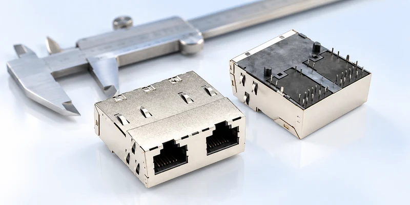
Build a comparison around the required configuration, not a ranking of the largest wattage. The following fields keep a PoE MagJack power rating tied to an auditable proposal.
| Comparison field | Information to obtain for each candidate |
|---|---|
| Component identity | Full part number, drawing number, revision and option selection |
| Power definition | PSE, PD or component rating; per port or complete assembly |
| Current and voltage | Named terminals, current basis, continuous/peak distinction and voltage |
| PoE implementation | PSE/PD role, pairsets, supported allocation and any non-standard operation |
| Electrical compatibility | Required PHY, magnetic schematic and specified signal limits |
| Thermal conditions | Reference temperature, loading pattern, enclosure and applicable limits |
| Evidence and exceptions | Relevant reports, remaining questions and approval responsibility |
Ask suppliers to respond to the same power location and operating case. If one offers only a portfolio-level 150W statement while another supplies model-specific current conditions, the documents are at different levels of detail. Request the missing evidence before comparing cost or describing the first proposal as the higher-performance choice.
Resolve discrepancies before sample approval. In the GLGNET example, the webpage/PDF part-number difference deserves a written clarification. The current controlled drawing should identify the configuration being quoted, the meaning of the power label and any qualification conditions that purchasing will need to retain. A drawing filename alone should not replace the complete approved identity.
Keep an exceptions column in the approval record. If the supplier has not defined simultaneous port loading, for example, that item remains open even when the sample operates on the bench. Assign each open question to the party providing the evidence and identify the required acceptance condition. This makes the eventual approval apply to a reproducible configuration rather than to a successful demonstration with undocumented limits.
For a multiport product, tell the supplier which ports must operate simultaneously and what the equipment power budget allows. A per-port capability does not establish the total power available from the switch supply. This keeps component selection aligned with the operating case the OEM can actually support, without assuming that every listed maximum occurs together.
The PoE magnetic RJ45 application selection guide covers the wider equipment decision. For this rating review, send GLGNET the PSE/PD role, required load-power location, pairset arrangement, PHY, port-loading pattern and worst-case operating environment. Request the matching high-power drawing and rating conditions before approving a sample from the magnetic RJ45 range.
PoE MagJack Power Rating FAQs
Does a 150W MagJack mean IEEE 802.3bt delivers 150W to the device?
No. The cited IEEE 802.3bt explanation distinguishes up to 90W at the PSE from 71.3W at the PD. A manufacturer's 150W component or portfolio description does not change that definition. Obtain the exact part, implementation and rating conditions before specifying a higher-power system.
Why do PSE and PD power ratings differ?
The channel between the two interfaces has losses. The source-side value therefore cannot be treated as power available at the PD input. Power usable by the equipment after conversion requires a further assessment using the actual converter and load conditions.
What evidence is needed before approving a high-power MagJack?
Obtain the controlled model drawing, current-path definition, voltage and thermal conditions, relevant magnetic specifications and applicable validation records. Keep component evidence separate from complete PSE/PD system qualification, and resolve any ordering-code or per-port rating ambiguity before releasing the BOM.
For related connector guidance, review the RJ45 gold plating thickness buying guide, the ganged vs. stacked magnetic RJ45 layout guide, the industrial Ethernet connector selection guide, the 2.5G vs 5G vs 10GBASE-T MagJack selection guide, and the high speed connector guide for AI data centers. Browse networking connectivity solutions or explore GLGNET’s magnetic RJ45 connector portfolio for more.