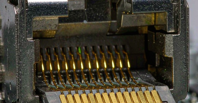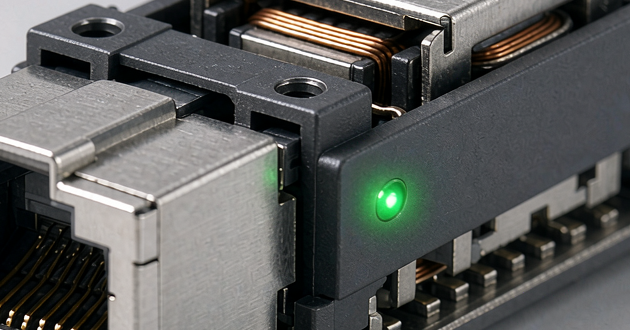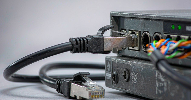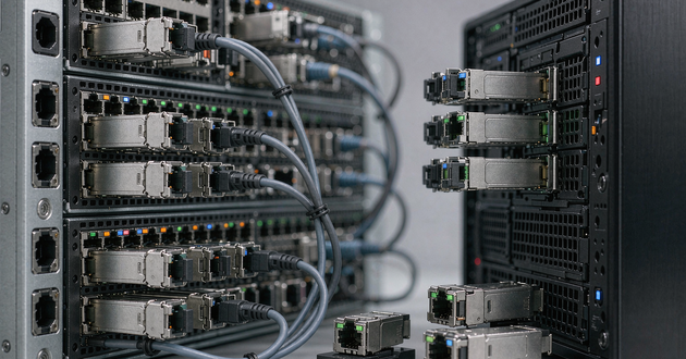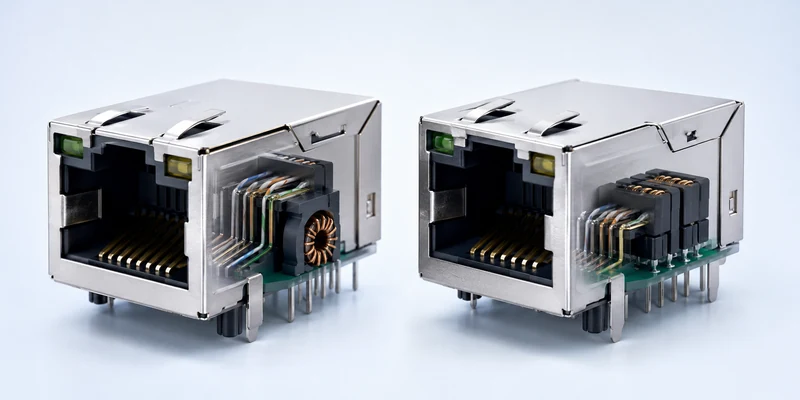
High speed connector performance is limited by the weakest part of the complete channel, not by the connector name or advertised port speed alone. In AI servers and network switches, insertion loss, return loss, crosstalk, PCB routing, module power, airflow, port density and mechanical tolerance all consume margin. A reliable design evaluates the host connector, cage, board, module and enclosure as one system.
For application-level product planning, review GLGNET AI data center connectivity solutions. If the interface family has not yet been selected, begin with the data center connector selection guide before evaluating detailed performance limits.
High Speed Connector Performance Starts With the Complete Channel
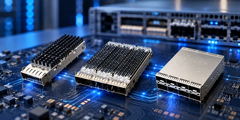
A high speed connector is only one discontinuity between the SerDes transmitter and receiver. The path can include package escape routing, PCB traces, vias, the connector footprint and contacts, a module card edge, and the front-panel assembly. Each element contributes loss, reflection, noise or timing error. Strong standalone S-parameter results cannot compensate for a poor PCB launch or module interface.
Aggregate port speed is therefore not a sufficient purchasing specification. The same 400G or 800G label may use different lane counts, per-lane rates, modulation and form factors. The system must match the host electrical interface, applicable MSA, footprint, cage and module architecture. Allocate the channel budget before part approval.
This view also separates supplier and system responsibility. A supplier can provide models, drawings and test data under stated conditions; the equipment designer must confirm that those conditions represent the actual stack-up, launch, enclosure and module.
Signal Integrity Limits From Insertion Loss, Return Loss and Crosstalk
Signal integrity becomes harder to preserve as frequency content rises and the eye opening becomes smaller. Three measurements show how the interconnect consumes margin.
Insertion loss measures signal attenuation between input and output. It increases with frequency and length and accumulates across traces, vias, contacts and cable. Excessive attenuation reduces receiver margin and increases dependence on equalization. Judge the complete channel across the required frequency range, not the connector at one frequency.
Return loss indicates energy reflected by impedance discontinuities. Contact geometry, pads, anti-pads, reference-plane changes and the module card edge can create mismatch. TDR helps locate the discontinuity, while frequency-domain data shows its effect across the operating band.
Crosstalk is unwanted coupling from adjacent pairs or nearby noise sources. Tighter spacing and weak grounding can increase it. Review near-end, far-end and power-sum behavior for multi-lane ports. Mode conversion and intra-pair skew also matter because an unbalanced transition can turn differential energy into radiation or noise.
These metrics belong together. Optimizing one while ignoring the others can produce a design that passes a narrow test but lacks system margin. Connector data should therefore be reviewed together with the PCB launch, routing, module interface and receiver assumptions rather than treated as an isolated pass-or-fail specification.
| Channel element | Typical performance risk | Evidence to request or generate |
|---|---|---|
| Package escape and PCB traces | Dielectric and conductor loss, skew, reference-plane discontinuity | Stack-up, route length, differential impedance and channel simulation |
| Vias and connector launch | Stubs, reflections and mode conversion | Recommended footprint, TDR and 3D electromagnetic model |
| Host connector and module card edge | Contact discontinuity, return loss, crosstalk and mating variation | Mixed-mode S-parameters and mated-interface data |
| Cage, panel and grounding | Radiated emissions and shielding discontinuity | Cage-to-panel contact design and enclosure-level EMI test |
| Module, cable or optical link | Added loss, power and thermal load | Module specification, link budget and operating-temperature limits |
PAM4 Bandwidth and QSFP Connector Channel Margin
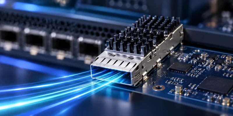
PAM4 carries two bits per symbol using four amplitude levels. It increases throughput without doubling the symbol rate, but divides the voltage range into smaller eyes. Noise, reflections, jitter and nonlinear distortion therefore consume more margin than in an NRZ link. A new lane-rate generation cannot be treated as the same hardware at a higher clock.
For a QSFP connector or another pluggable I/O system, the required electrical performance must be tied to the actual lane rate and modulation, not only to aggregate port bandwidth. The equipment team should confirm the host specification, lane count, target reach, equalization assumptions and required interoperability. A cage may appear mechanically compatible across several module generations while the host connector, footprint, thermal design or validation limits differ.
Industry development toward 224 Gb/s-per-lane signaling and 1.6T links explains why PCB loss and connector discontinuities are receiving more attention. This roadmap context must not be treated as a product capability claim. GLGNET's public AI data center page states that its SFP and QSFP portfolio covers 1G to 800G applications depending on the selected series and interface configuration. Any higher lane-rate requirement should be checked against a specific part number, model and validation report before it is included in a design.
As the loss budget tightens, designers may shorten PCB traces, move the interface closer to the ASIC, use low-loss materials, route critical signals through twinax, add active conditioning or transition to optics. The decision balances reach, power, latency, heat, serviceability and cost; there is no universal distance at which optics always replaces copper.
Thermal Management and Port Density for AI Data Center Connectors
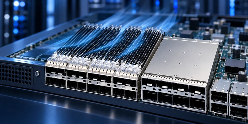
Thermal management is electrically relevant because high-speed ports operate inside the same constrained front-panel area as heat-generating transceivers, switch silicon and power-delivery components. Higher port density can reduce available airflow, place adjacent modules in each other's thermal wake and limit heat-sink width or travel. A layout that maximizes the number of cages across the panel may therefore reduce the operating margin of the modules installed in those cages.
Begin with module power, inlet-air temperature, airflow direction and component limits. Then review cage spacing, heat-sink pressure and fin orientation, stacked arrangements and rear-panel obstructions. Thermal simulation supports layout, but the final assembly still needs measurements under representative traffic, module population and fan conditions.
Temperature also changes the tolerance stack, while repeated cycling can stress solder joints, press-fit interfaces and contact surfaces. A generic rating is not enough; qualify the connector, cage, PCB, panel and module combination over the intended operating profile.
The same density tradeoff affects EMI. A conductive cage is most effective when its spring fingers and grounding features make consistent contact with the panel and PCB ground structure. Gaps, coating at the contact area, panel misalignment or inadequate grounding vias can weaken shielding even if the cage material itself is correct. EMI performance must therefore be evaluated in the intended enclosure rather than inferred from an isolated cage.
QSFP Cage, PCB Layout and Mechanical Tolerance Effects
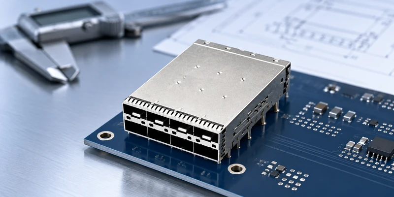
A QSFP cage performs several jobs at once: it guides and retains the module, connects the shield to the chassis and board ground, supports heat-sink or light-pipe options, and establishes the mechanical path from the PCB to the front panel. Those functions make mechanical tolerances part of high-frequency performance.
The PCB footprint should follow the released connector drawing rather than a visually similar legacy layout. Pad geometry, anti-pads, via transitions and ground-via placement affect impedance and coupling. Differential pairs should remain length-matched and geometrically balanced through the launch, with unnecessary stubs removed and reference-plane changes controlled. Routing a pair correctly up to the connector but ignoring the launch can leave the largest discontinuity at the interface itself.
Mechanical review should freeze the connector and cage datums, board thickness, panel cutout, keep-out zones, press-fit or solder process, heat-sink travel, light-pipe routing and module extraction clearance. For ganged or stacked cages, cumulative tolerance and PCB bow can affect alignment across the full array. Press-fit force, hole specification and tool support must also be compatible with the board process; substituting a cage based only on port count can create assembly damage or unreliable grounding.
This is where keyword categories such as sfp cage, sfp28 cage and QSFP products must remain distinct. They describe different host interfaces and should not be treated as interchangeable solutions merely because their purpose appears similar. The correct family follows the module form factor and host architecture; the exact cage configuration then follows the mechanical, thermal and EMI requirements.
Connector Validation for High-Speed AI Data Center Links
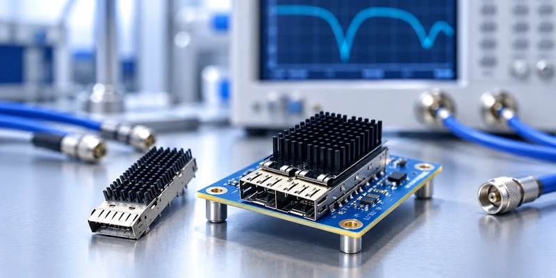
Reliable validation progresses from models to a representative system. Request the drawing, PCB footprint, material and plating definition, applicable MSA and mixed-mode S-parameters. The fixture, reference planes, de-embedding method and mated configuration must be stated or apparently similar plots may not be comparable.
Combine the model with the actual package, stack-up, traces, vias and module interface. Review loss, crosstalk, mode conversion and time-domain impedance, then evaluate eye or protocol-specific results. Laboratory work can include VNA/TDR measurements, BER testing and correlation with the manufactured test board.
Follow electrical qualification with enclosure-level EMI, thermal and mechanical tests. Populate adjacent ports, use representative modules and operate the intended cooling hardware. Select mating durability, contact resistance, retention, vibration and thermal cycling tests for the actual equipment environment.
| Gate | Approval question | Minimum evidence |
|---|---|---|
| Component | Does the connector meet the required interface under stated conditions? | Drawing, footprint, material specification and S-parameters |
| Channel | Does the real route retain sufficient electrical margin? | Stack-up-aware simulation, TDR/VNA and eye or protocol metric |
| Mechanical | Will the board, cage, panel and module align through tolerance? | Tolerance analysis, assembly trial and insertion/extraction check |
| Thermal and EMI | Does the populated enclosure remain inside limits? | Representative thermal measurements and enclosure-level EMI results |
| Production | Can the process reproduce the qualified build? | Inspection criteria, process controls, sample records and change control |
After approval, lock the drawing revision, plating, materials, tooling, inspection and change-notification process. One passing sample is insufficient if later substitutions can alter the contact, resin, shielding or heat-sink interface.
Selecting SFP Connectors and QSFP Connector Solutions With GLGNET
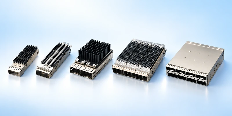
GLGNET supplies equipment-side SFP, SFP+, SFP28 and QSFP-family connectors and cages for switches, servers, network cards and data center hardware. Available configurations described in the company materials include single, ganged and stacked port arrangements, with options such as heat sinks, light pipes and EMI shielding. Review the current QSFP connector and cage solutions or SFP28 cages and connectors for 25G links according to the host interface.
The GLGNET company profile describes an SI team with six CAE engineers supporting simulation, testing, result analysis, debugging and test-board design. Listed laboratory resources include PNA, VNA with switching capability and temperature-rise testing, alongside environmental and mechanical equipment. These capabilities are relevant because connector qualification requires electrical, thermal and mechanical evidence to converge on the same design.
For a useful engineering review, send the equipment type, protocol, aggregate port speed, lane rate and count, module form factor, target reach, PCB stack-up and route length, panel and board drawings, port map, mounting process, module power, airflow, ambient condition, EMI target and required qualification standard. GLGNET can then review the connector, cage, heat-sink and layout inputs as a system instead of selecting a part from bandwidth alone.
AI Data Center Connector FAQ
What affects high-speed connector performance?
Performance is affected by the entire transmitter-to-receiver path: PCB material and route length, vias, connector launch geometry, contact impedance, crosstalk, module card edge, cable or optical interface, thermal conditions and mechanical alignment. The connector part number alone cannot predict the finished channel. Evaluate component data together with the real board stack-up, enclosure and module.
Why does insertion loss matter in a connector channel?
Insertion loss reduces the signal energy reaching the receiver and consumes the channel's available margin. It rises with frequency and accumulates across every trace, via, connector and cable segment. Excessive loss can shrink the eye opening and increase reliance on equalization. Compare loss across the required frequency range and for the complete channel, not at a single frequency point.
What is the typical speed of data center internet?
There is no single typical speed. Conventional server access links may use 25G, 50G or 100G, while AI backend networks increasingly use 400G and 800G links between GPUs and switches. Industry roadmaps are moving toward 1.6T. The connector choice still depends on the per-lane electrical interface, lane count, form factor and reach rather than the aggregate network label alone.
How are high-speed connectors validated?
Validation normally combines supplier drawings and S-parameters, channel simulation, TDR or VNA measurements, eye or protocol-specific analysis, and representative thermal, EMI and mechanical tests. The fixture, de-embedding method, reference planes, frequency range and mated configuration must be documented. Final approval should use the intended PCB, cage, panel, module and cooling conditions.
Does a connector rated for 800G guarantee an 800G port will work?
No. An aggregate rating does not guarantee that the board route, module, cage, thermal design and complete channel meet the required interface. Confirm the lane architecture, modulation, host specification and validated conditions behind the rating. The system must retain enough margin after all channel elements and operating variations are included.
When should a design move from PCB copper to cable or optics?
Move away from a long PCB route when its loss, reach, routing density or thermal cost no longer fits the channel budget. Low-loss twinax can move critical signals across the board or chassis, active copper can extend some short links, and optics can provide longer reach and isolation. The correct transition point depends on architecture, power, latency, serviceability and cost rather than one universal distance.
Send GLGNET your interface specification, board and panel drawings, module power and target validation requirements to review a suitable connector and cage configuration for your AI server or network-switch project.
For related connector selection guidance, review the data center connector selection guide for AI servers and network switches, the SFP port connector selection guide for switch and NIC host boards, the industrial Ethernet connector guide, the PoE magnetic RJ45 connector guide, the MagJack cross-reference guide, and the 2.5G vs 5G vs 10GBASE-T MagJack selection guide. Browse GLGNET’s magnetic and high-speed connector portfolio or explore networking connectivity solutions for more.