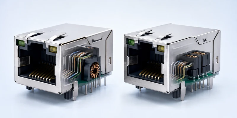
Selecting an SFP electrical connector starts with the host system, not with the appearance of the port. Define the Ethernet or Fibre Channel rate, host SerDes interface, transceiver family, PCB and bezel geometry, cage configuration, assembly process, EMI strategy and operating environment before approving a part. The host receptacle must mate with the intended module, fit the selected cage and footprint, and remain reliable across the complete switch or network interface card design.
For equipment developers building high-speed data connectivity solutions, this system-level approach prevents a common mistake: choosing a connector because the module slides into the cage, only to discover later that the footprint, signal channel, grounding, thermal path or production process is incompatible.
What an SFP Port Connector Does on a Host Board?
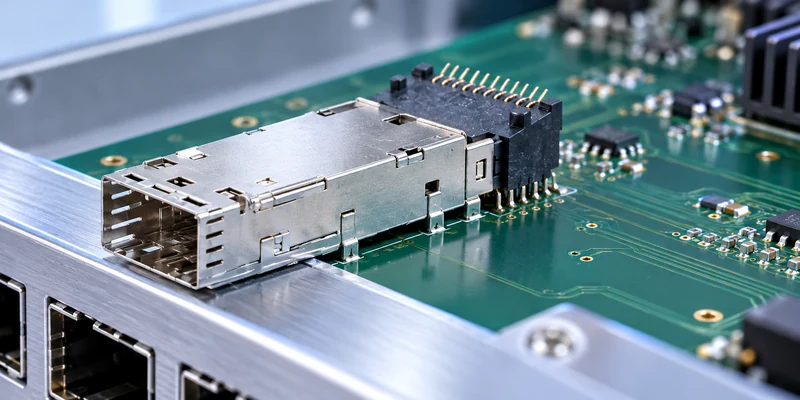
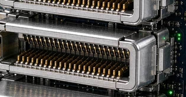
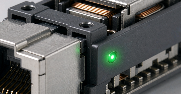
An SFP host interface contains several components that are easy to confuse. The transceiver is the removable module. The metal cage guides and retains that module while contributing to EMI containment and, in some designs, thermal management. The external LC or RJ45 interface belongs to the transceiver. The PCB-mounted electrical receptacle at the rear of the cage is the component that mates with the module's card-edge pads and connects the module to the host electronics.
Standard SFP-family modules use a 20-position host electrical interface. That does not mean every 20-position receptacle is suitable for every SFP generation. Contact design, housing geometry, data-rate qualification, cage relationship and PCB footprint must match the host architecture. A nominally compatible part can create rework if its datum, standoff height or land pattern differs from the approved drawing. Procurement databases may also describe this family as sfp small form factor pluggable connectors, but the actual drawing remains the design authority.
The connector cannot be evaluated independently from the channel. In a switch, it sits between the front-panel module and dense routing to the switch ASIC or PHY. On a NIC, it must align with the bracket and coexist with the PCIe interface, heat sources and chassis airflow. The same form factor can therefore produce different mechanical and thermal decisions. GLGNET's SFP cages and connectors are intended for these host-side applications rather than cable termination.
Match SFP Connector Types to the Required Data Rate
| Host-port target | Connector and cage family to review | Main design check | Typical equipment context |
|---|---|---|---|
| 1G Ethernet | SFP | Module and MSA fit, 20-position interface, basic EMI and thermal needs | Access switches, industrial gateways and legacy NICs |
| 10G Ethernet | SFP+ | Connector signal performance, cage grounding, loss budget and module power | Enterprise switches, servers and 10G NICs |
| 25G Ethernet | SFP28 | Full 25G channel performance, tighter layout control, module heat and port density | Data-center switches, storage and 25G adapters |
The first electrical decision is the rate the host will support. SFP is commonly associated with 1G links, SFP+ with 10G, and SFP28 with 25G. They retain a similar compact format and use one high-speed transmit lane and one receive lane, but higher-rate versions impose tighter channel requirements. Mechanical similarity is not proof that the connector, PCB channel, module and firmware will operate at the requested rate.
Start with the switch ASIC, PHY or NIC controller data sheet and system link budget. Confirm the electrical standard, signaling rate, equalization assumptions and permitted PCB-channel loss. Then choose the relevant sfp connector types and request data for that rate. A part described only as SFP-compatible may still lack the evidence needed for a 10G or 25G channel.
This boundary also protects the site's content architecture. Readers designing 10G equipment can compare 10G SFP+ cages and connectors, while 25G projects should move to 25G SFP28 cages and connectors. The host connector should be selected for the rate implemented on the board, not for a future rate that the SerDes, stack-up or firmware cannot support.
Check the SFP Module Connector Against the Host Interface
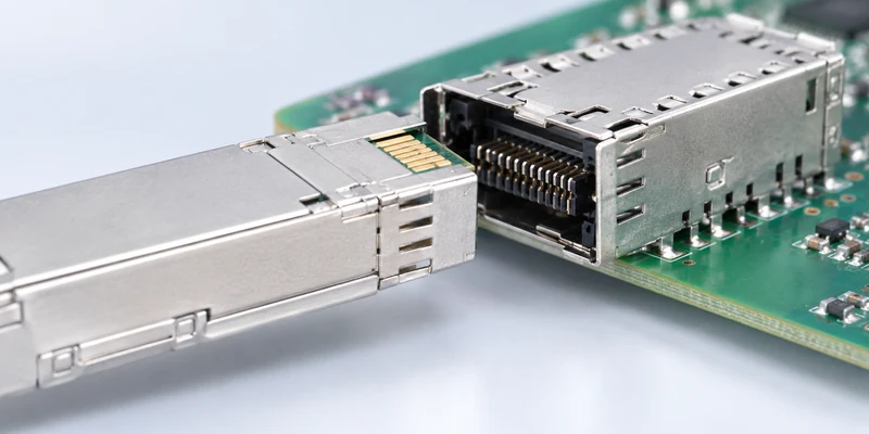
After choosing the rate family, verify the complete mating interface. The sfp module connector on the host side should be checked against the applicable MSA or SFF mechanical requirements and, more importantly, against the supplier's current product drawing. Review circuit count, contact pitch, contact plating, housing material, coplanarity, orientation, module stop position and the exact SMT land pattern. Do not transfer a footprint from another vendor's drawing merely because both parts are described as SFP.
The 20 positions include high-speed transmit and receive pairs, grounds, power and low-speed management or status signals. Pin assignment and power sequencing need to follow the selected module interface and host controller design. The connector is only the physical path; the host must also provide the correct power filtering, control logic, module-presence handling and management interface. A connector cannot correct an incorrect pin map or an unsupported module-power budget.
Contact durability deserves the same attention as initial fit. Ask for operating temperature, plating, mating-cycle basis and material information for the exact part number. A sample that works for several insertions is not evidence of long-term performance in equipment that may experience repeated module changes.
Hot-plug capability is a system property. Safe insertion and removal depend on host power design, contact sequencing, controller behavior and firmware; hot-swappable should not be treated as a connector-only guarantee.
Plan the SFP Connection Around PCB and Front-Panel Geometry
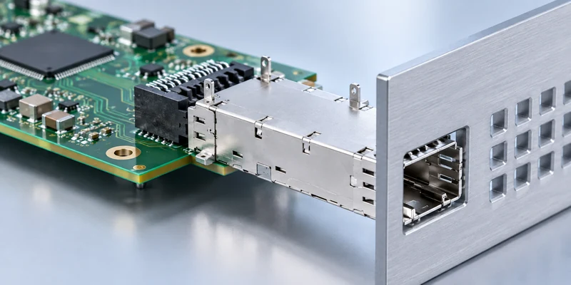
Mechanical layout should be frozen as a coordinated stack of module, cage, connector, PCB and bezel. Place the connector using the supplier's datum scheme, then confirm the distance to the PCB edge, cage mounting-hole pattern, keepout areas, module travel path and front-panel opening. Small errors in this stack can prevent the module latch from engaging, place stress on the receptacle or leave an ineffective EMI gap at the bezel.
The PCB routing must preserve the high-speed sfp connection from host silicon to module. Manage differential-pair spacing, discontinuities, layer transitions and return paths consistently, and keep signals out of cage keepouts and chassis-ground regions. Geometry and length limits should come from the PHY or ASIC guide and board analysis, not from a universal rule copied from another product.
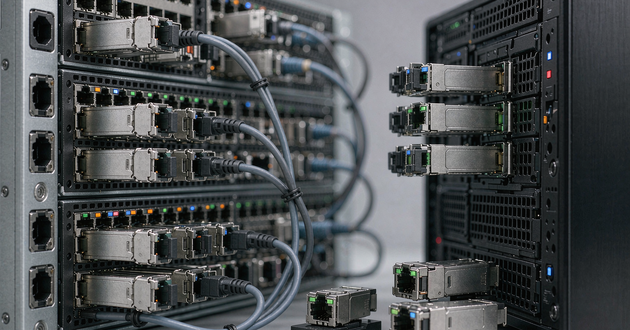
Switches and NICs emphasize different constraints. A switch may use 1xN or 2xN arrays, making cage pitch, airflow, light-pipe routing and grounding critical across adjacent ports. A NIC has fewer ports but tighter alignment between the connector, cage, card bracket and server chassis. Both require a tolerance review covering the PCB, cage, connector, panel and module.
Pair the SFP Cage Connector With the Correct Mounting Method
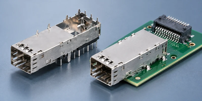
The cage and receptacle should be qualified as one mechanical and EMI system. A suitable sfp cage connector combination keeps the module aligned with the contacts, maintains the intended insertion depth and provides a controlled shield path to the bezel and chassis ground. Select the cage configuration only after port count, panel pitch, board space and airflow have been established.
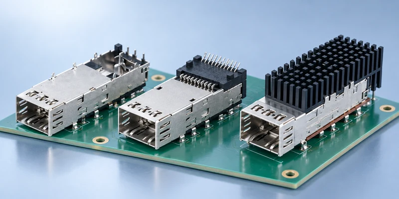
Single 1x1 cages simplify prototyping and low-port-count layouts. Ganged 1xN cages reduce part count and control port spacing across a switch faceplate. Stacked 2xN designs increase density but require closer attention to thermal gradients, light-pipe placement, press tooling and access for inspection or repair. Optional heat sinks, riding clips, light pipes and EMI gasket styles must be included in the tolerance and assembly review because they change the complete stack.
In many designs, the electrical host connector is SMT while the cage uses compliant press-fit tails or solder posts. A press fit sfp cage can provide mechanical retention and avoid an additional cage-soldering operation, but it requires the correct PCB thickness, finished-hole specification, plating, insertion tool and force control. Solder-tail cages impose different thermal and process constraints. The manufacturing team should approve the mounting method before samples are ordered, particularly for stacked ports or boards with components on both sides.
Do not assume a cage and connector from different series will work together because they share a nominal form factor. Request a matched drawing set and verify connector position, cage datum, tail pattern, bezel engagement, latch clearance and rework method, especially when qualifying a second source without changing the PCB.
Evaluate SFP Connectors for Signal Integrity, EMI and Thermal Conditions
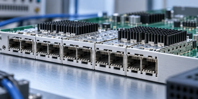
At higher data rates, sfp connectors must be evaluated as part of the full channel. Connector-only performance data is useful, but the production board adds launches, vias, differential routing, reference-plane transitions and the module interface. Review insertion loss, return loss and crosstalk over the relevant frequency range, then correlate simulation with a representative test board when the project risk justifies it. The pass/fail criteria should come from the host standard and silicon guidance.
EMI performance depends heavily on the cage-to-chassis path. Spring fingers or gaskets should make reliable contact with the bezel, while cage pins, chassis-ground pads and nearby vias create a low-impedance return path. A shielded cage cannot compensate for a large panel gap or a long, poorly connected ground path. On a dense switch, adjacent ports and high-speed clocks can make these discontinuities more visible than they are on a single-port prototype.
Thermal review begins with the maximum power of the intended optical, copper or cable module and the worst expected inlet-air condition. Check the cage ventilation, system airflow, neighboring heat sources and whether a heat sink or enhanced cage is required. Copper modules and higher-rate optics can impose different power profiles even when they fit the same opening. The connector material temperature rating is necessary, but it does not replace module-case and system-airflow analysis.
Validation should reflect the host environment, including temperature, humidity, ESD, vibration or shock, repeated insertion and contamination where applicable. GLGNET's company material identifies electrical, environmental and mechanical laboratory capabilities, including IEEE compliance equipment, PNA and VNA-based testing. Test plans and limits should still be agreed for each project and part number.
What to Ask SFP Cage Manufacturers Before Production?
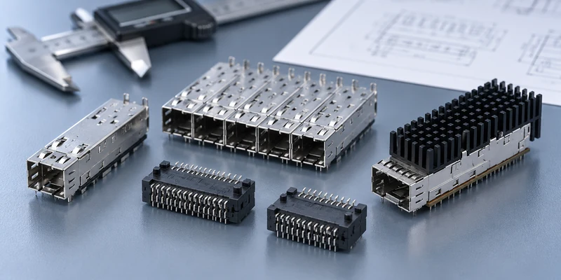
Effective sourcing starts with an engineering package rather than a short request for an SFP price. When contacting sfp cage manufacturers, provide the target rate, SFP family, port matrix, board thickness, PCB stack-up constraints, connector mounting method, cage mounting method, bezel drawing, operating temperature, module-power range, EMI target and any light-pipe or heat-sink requirement. Include an approved reference part, mechanical drawing or physical sample when the project involves second-source qualification.
Ask the supplier to return matched connector and cage part numbers, current drawings, recommended PCB layout, material and plating information, packaging, compliance documents and available test evidence. For custom features, define controlled dimensions, sample-phase validation and changes that require requalification.
Before release, validate five areas. Mechanical checks cover insertion, latch operation, bezel fit and alignment. Assembly checks cover SMT solder quality, press-fit compatibility, insertion force and board damage. Electrical checks cover continuity, power, management functions and the high-speed channel. EMI and thermal checks use the actual enclosure and airflow, while reliability checks reflect expected temperature and mating duty.
GLGNET's portfolio includes SFP, SFP+, SFP28 and other high-speed I/O families in multiple 1xN and 2xN configurations. Its published company profile also describes mechanical design, electrical engineering, simulation and laboratory support. For a new switch or NIC, use GLGNET's custom connector engineering support to review the host-board requirements before committing the PCB and front-panel tooling.
SFP Connector Types FAQ
What is an SFP electrical connector?
An SFP electrical connector is the PCB-mounted host receptacle behind the SFP cage. It mates with the 20-pad card edge of a compatible pluggable module and carries high-speed transmit and receive signals, power, ground and management signals between the module and the host system. It is different from the cage, the transceiver and the external LC or RJ45 interface on the transceiver.
Are SFP and SFP+ host connectors the same?
SFP and SFP+ share a similar module form factor and 20-position host interface, but that does not make every connector or complete host design interchangeable. The connector, cage, PCB channel, host SerDes and firmware must be qualified for the required rate. A part approved for a 1G design should not be assumed to support 10G solely because an SFP+ module can be inserted mechanically.
How many pins does an SFP host connector have?
A standard SFP-family host connector has 20 positions that mate with the module's edge pads. These positions serve high-speed differential signals, grounds, power and low-speed control or status functions. Designers should use the applicable interface specification and the selected connector drawing when assigning the footprint and pin functions.
Does an SFP host board need both a connector and a cage?
Most front-panel SFP host designs use both. The electrical connector provides the PCB-to-module contacts, while the cage guides and retains the module and contributes to EMI containment, bezel grounding and sometimes thermal management. Integrated or specialized assemblies also exist, so the final architecture should follow the selected product family and equipment layout.
Can one SFP port accept both optical and copper modules?
The standardized host opening may accept compatible optical, copper or cable modules, but successful operation depends on more than physical fit. The host must support the module's data rate, electrical interface, firmware or management requirements, power consumption and thermal load. Confirm the switch or NIC controller specifications and the intended module list before release.
Is an SFP connector hot-swappable?
SFP-family interfaces are intended for pluggable-module operation, but hot-swap reliability is a system-level result. Correct contact sequencing, host power control, presence detection, firmware behavior, cage alignment and ESD design all matter. The complete board and enclosure should be validated with the intended modules under realistic operating conditions.
Choose an SFP Port Connector With GLGNET
The most reliable selection process treats the host receptacle, cage, PCB, bezel, module and production process as one interface. Send GLGNET your target data rate, port arrangement, board and panel drawings, mounting method, module-power range, EMI and thermal requirements, and any approved reference part. The engineering team can help compare suitable SFP-family connector and cage options for sample evaluation. Contact GLGNET to review your switch or NIC host-board design.
For other connector selection guides, also review the 2.5G vs 5G vs 10GBASE-T MagJack selection guide, the MagJack cross-reference guide, the data center connector selection guide for AI servers and network switches, the industrial Ethernet connector guide, and the PoE magnetic RJ45 connector guide. Browse GLGNET’s magnetic RJ45 connector portfolio or explore networking connectivity solutions for more.