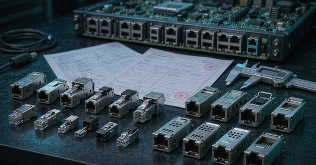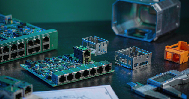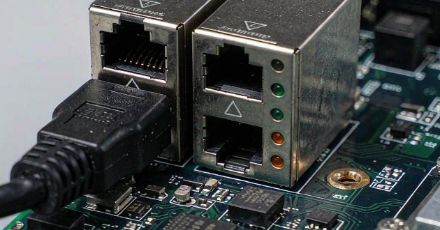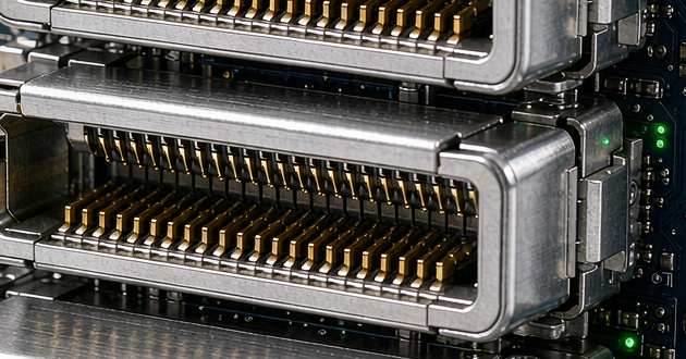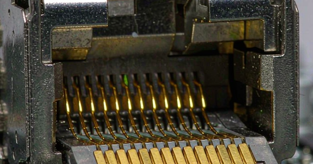
A MagJack cross reference is not a simple exercise in finding another connector with the same port count and a similar metal shell. An RJ45 with integrated magnetics contains the connector, isolation transformers, common-mode chokes, center-tap connections and sometimes PoE power paths, LEDs and termination components in one assembly. Two parts can look interchangeable while using different PCB holes, signal pins or internal magnetic circuits.
The safest replacement process therefore has two stages. First, compare the reference part and candidate replacement on paper: mechanical drawing, footprint, pinout, transformer circuit, Ethernet rate, PoE rating and environmental limits. Second, validate the selected candidate on the actual PCB. Until both stages are complete, describe the new part as a candidate replacement for evaluation—not a guaranteed 100% drop-in replacement.
Why a MagJack Cross Reference Cannot Rely on External Appearance
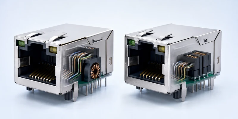
The front opening of most PCB-mounted RJ45 products follows the familiar 8P8C interface, so many connectors appear nearly identical from the panel side. That similarity says very little about board compatibility. The plastic locating posts, shield tabs, signal-pin rows, LED leads, board locks and connector height may all differ. Even a shift of less than a millimeter can prevent insertion into an existing PCB or move the port out of alignment with the enclosure cutout.
The hidden differences are more important. A standard RJ45 jack is mainly a mechanical interface, while an ICM includes magnetics selected for a particular Ethernet architecture. A compatible magnetic RJ45 must preserve both the mechanical interface and the electrical behavior expected by the PHY. Matching only the housing can produce a part that fits the panel but fails to link, performs poorly in EMC testing or overheats under PoE load. For the underlying product distinction, see RJ45 with magnetics vs. standard RJ45.
Start the RJ45 Replacement by Part Number and Original Evidence

Begin with the complete manufacturer and part number printed on the BOM, datasheet or component. Avoid working from an abbreviated marking alone because similar codes may represent different LED colors, PoE circuits, temperature grades or pinouts. Collect the original datasheet, recommended PCB layout, internal schematic and the Ethernet PHY reference design used on the board. If the original datasheet is unavailable, provide the PCB drawing, clear photos of every side and a physical sample.
The application information is equally important. Record whether the port is PSE or PD, the required Ethernet rate, supported fallback rates, maximum ambient temperature, port density and assembly process. A supplier can narrow a MagJack replacement much faster when the request includes the exact PHY number and PoE requirement instead of only asking for “something similar.” For a broader view of available structures, review the GLGNET Magnetic RJ45 connector range.
Compare the MagJack Footprint and Mechanical Drawing
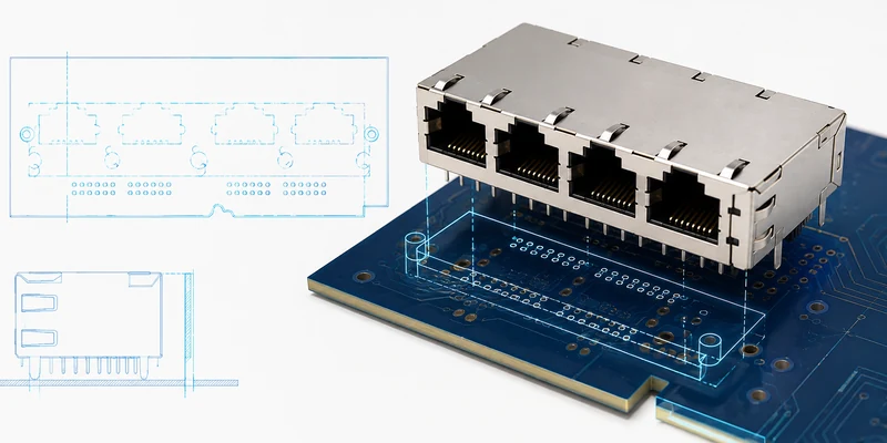
Overlay the two recommended PCB layouts at the same scale. Confirm signal-pin diameter and pitch, row spacing, locating-post diameter and position, shield-tab geometry, board-lock position and any keepout areas. Then compare overall length, width and height, port centerline, board-edge offset, latch-up or latch-down orientation and panel opening. A nominally right-angle 1×1 connector may still require a different hole pattern or sit at a different height above the PCB.
For multi-port parts, compare more than the number of openings. A 1×4 ganged MagJack and a stacked 2×2 design place loads, shields and LEDs differently. Check coplanarity and solder-tail length against the assembly process. Through-hole DIP, pin-in-paste, SMT and press-fit versions are not automatic substitutes, even when the front dimensions match. The drawing comparison should end with a clear result: exact match, acceptable with documented tolerance, or PCB/enclosure change required. For general form-factor decisions beyond a replacement project, use the RJ45 jack connector selection guide.
Match the RJ45 Integrated Magnetics Transformer Circuit, Turns Ratio and Center Tap
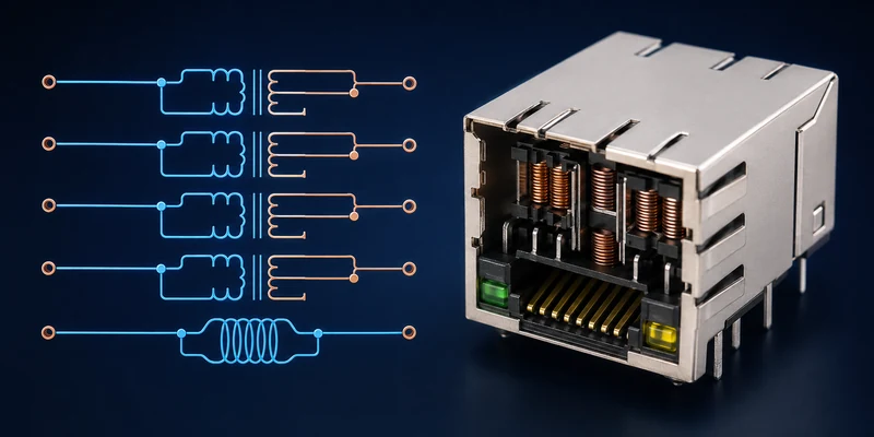
The internal schematic is the decisive electrical comparison. Review the number and placement of isolation transformers and common-mode chokes, transformer turns ratio, center-tap access, Bob Smith or other cable-side termination, and any integrated resistors or capacitors. The same speed label does not prove that two internal circuits are equivalent. A 1CT:1CT transformer notation, for example, must be interpreted together with the center-tap routing and PHY reference circuit.
Center taps may provide bias, decoupling or PoE access depending on the design. Connecting them according to another vendor’s generic drawing can be unsafe because the required arrangement depends on the PHY and whether the port is a power sourcing equipment or powered device interface. Compare the candidate schematic line by line with the original and the PHY vendor’s current reference design. If the candidate datasheet does not disclose enough internal detail, request an engineering drawing before approval.
Verify MagJack PHY Pinout and Current-Mode or Voltage-Mode Compatibility
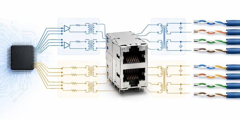
A MagJack PHY pinout comparison must follow the signal path, not just pin numbers. Map each MDI pair from the PHY through the transformer to the cable contacts. Confirm polarity, pair assignment, center-tap pins, chassis and signal-ground connections, and any unused or no-connect pins. Also verify that LED pins have not been mistaken for signal or ground connections.
Current-mode and voltage-mode PHYs can require different center-tap and termination arrangements. Some newer ICMs are designed to support both architectures, but that capability should be supported by the datasheet or written manufacturer confirmation for the selected PHY family. The practical rule is simple: the candidate must match the exact PHY reference schematic on the existing board. Generic claims such as “compatible with all PHYs” are not enough for a production change.
Check MagJack Data Rate, Return Loss and PoE Current Rating

Confirm the required Ethernet standard—10/100BASE-T, 1000BASE-T, 2.5GBASE-T, 5GBASE-T or 10GBASE-T—and every fallback rate the product must negotiate. Higher nominal speed is not a substitute for compatibility. Compare open-circuit inductance, insertion loss, return loss, crosstalk, common-mode rejection and isolation voltage across the frequency range relevant to the design. If the original qualification depended on a specific surge or hi-pot level, include that requirement as well.
PoE must be checked separately from data rate. Determine whether the design follows IEEE 802.3af, 802.3at or 802.3bt, whether it uses two-pair or four-pair power, and the required current per pair. Compare winding resistance, contact resistance, current rating and available temperature-rise data. A connector advertised for Gigabit or 10G is not automatically suitable for PoE++, and a headline wattage does not prove safe operation in a sealed enclosure or a high-density switch. GLGNET supports PoE options across its magnetic RJ45 portfolio, but the exact circuit and thermal limits still need project-level confirmation.
Confirm Compatible Magnetic RJ45 LEDs, Shielding, Grounding and Materials
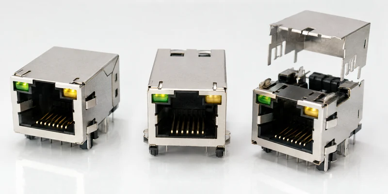
LED differences can prevent a mechanically compatible part from working correctly. Compare left and right LED positions as viewed from the mating face, color, single-color or bi-color construction, polarity, forward voltage and internal resistor arrangement. The enclosure may also use a light pipe or front-panel legend that makes the physical LED location part of the product requirement.
Next compare the metal shield, EMI fingers, chassis-ground tabs and gasket interface. The candidate should preserve the intended low-impedance connection from connector shield to chassis without violating the isolation boundary around the PHY. For industrial or outdoor equipment, also match contact plating, housing flammability rating, soldering temperature, operating range and resistance to humidity, vibration or corrosive environments. GLGNET’s networking connectivity solutions page provides application context for switches, routers, access points, servers and industrial networking equipment.
Validate the MagJack Replacement with Samples and Board-Level Testing

Paper comparison identifies a credible alternative; it does not release the part for production. Obtain samples from the intended manufacturing source and inspect dimensions, pin finish, marking and packaging. Assemble them using the production soldering profile, then check alignment, solder joints, shield contact, LED operation and cable insertion. Confirm link establishment and auto-negotiation at all required rates with representative link partners and cable lengths.
Electrical validation should reflect the risk of the application. Measure or test the parameters relevant to the design, such as packet stability, bit error behavior, return loss, emissions, immunity, isolation, surge performance and PoE temperature rise at maximum load. Run the test at the highest expected ambient temperature and with realistic port density and airflow. Industrial products may also need thermal cycling, humidity, vibration and mating-cycle checks. Review common RJ45 MagJack design mistakes before final board approval.
What GLGNET Needs to Recommend an RJ45 with Integrated Magnetics Alternative
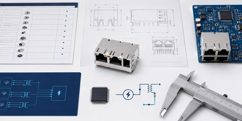
To start a MagJack cross reference, send the full reference part number and original datasheet if available. Include the PHY manufacturer and full device number, the relevant reference schematic, target Ethernet rate, PoE standard and power level, port configuration, mounting process, LED requirements, shielding details, operating temperature and enclosure limits. For an existing board, add the PCB footprint or Gerber extract and clear product photos. A physical sample is useful when documentation is incomplete.
GLGNET can use this information to screen its magnetic RJ45 portfolio for electrical and mechanical candidates, compare drawings and prepare samples for evaluation. The resulting recommendation should be treated as a candidate replacement until the customer confirms it on the actual PCB and completes the required compliance and reliability tests.
MagJack Cross-Reference Qualification Checklist
| Area | What must match | Required evidence |
|---|---|---|
| Identity | Manufacturer, full reference part number, revision | Original datasheet/BOM |
| Mechanical | Footprint, posts, shield tabs, height, latch, panel cutout | Overlayed drawings/sample |
| Magnetics | Transformer topology, turns ratio, center taps, chokes, termination | Internal schematics |
| PHY | Pair mapping, polarity, current/voltage mode, bias network | PHY reference design |
| Data | Ethernet rates, insertion/return loss, crosstalk, isolation | Datasheet and board tests |
| PoE | Standard, pair set, current, DCR and temperature rise | PoE circuit and thermal test |
| Interface | LED circuit, shield, grounding and EMI fingers | Drawing/schematic/inspection |
| Environment | Temperature, materials, soldering, reliability | Qualification reports |
| Release | Samples tested on production PCB and enclosure | Engineering approval record |
MagJack Cross-Reference FAQ
Can two MagJacks with the same dimensions have different pinouts?
Yes. Signal pins, center taps, LED leads, shield tabs and internal magnetics can differ even when the outer dimensions are nearly identical. Compare both PCB layout and internal schematic.
Can a higher-speed MagJack replace a lower-speed part?
Not automatically. The candidate still has to match the PHY topology, footprint, pinout, magnetic performance, PoE circuit and environmental requirements. A higher speed label only indicates bandwidth capability.
Is a supplier cross-reference enough to approve a drop-in replacement?
It is a useful starting point, not final approval. The customer should review controlled drawings and validate samples on the actual board under required data, EMC, PoE, thermal and reliability conditions.
What is the fastest way to obtain a candidate MagJack replacement?
Send the complete reference part number, datasheet, PHY number, PoE requirement and PCB drawing together. This allows mechanical and electrical screening to happen in parallel and reduces repeated sample rounds.
SEND YOUR REFERENCE PART NUMBER
Share the existing part number, PHY, PoE requirement, PCB footprint and operating conditions. GLGNET will help identify a candidate RJ45 with integrated magnetics alternative for drawing review and sample validation.