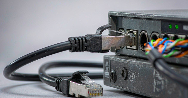
Direct answer: Fast Ethernet can be adequate for an individual IP camera when its worst-case combined video traffic stays comfortably below 100 Mbps. For new NVR uplinks, PoE switch uplinks, multi-sensor cameras, or systems expected to expand, a gigabit RJ45 connector and 1000BASE-T port are usually the safer design choice. Select the board-level connector from the Ethernet PHY, port role, PoE architecture, magnetic circuit, and thermal environment—not from camera resolution alone.
Fast Ethernet vs Gigabit RJ45 Connector: What Changes?
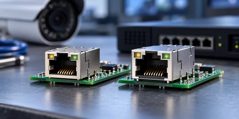
Fast Ethernet normally refers to 100BASE-TX at a nominal 100 Mbps. Gigabit Ethernet over copper normally refers to 1000BASE-T at 1,000 Mbps. Both commonly use an 8P8C modular interface, so a cable plug may fit both ports, but the host-board electrical requirements are not interchangeable. 100BASE-TX uses two data pairs, whereas 1000BASE-T uses all four pairs simultaneously. A 1000BASE-T RJ45 implementation therefore needs four suitable magnetic channels, a compatible PHY interface, controlled routing, and a cable channel that supports the intended rate.
The choice depends on where the port sits. A camera edge port normally carries one device’s streams. An NVR LAN port or PoE switch uplink aggregates many cameras and may also serve live view, playback, export, and remote clients. A 100 Mbps camera port may be reasonable while a 100 Mbps NVR uplink becomes the bottleneck. Decide by port role rather than assigning one speed to every connector.
| Design point | Fast Ethernet RJ45 | Gigabit Ethernet RJ45 |
|---|---|---|
| Nominal copper Ethernet rate | 100 Mbps | 1,000 Mbps |
| Data pairs used | Two pairs for 100BASE-TX | Four pairs for 1000BASE-T |
| Typical role in a new surveillance design | Cost-sensitive single-camera port after bandwidth verification | NVR LAN/uplink, PoE switch uplink, dense or expandable camera systems |
| Magnetic requirement | Two data channels may be sufficient for 10/100 PHY designs | Four compatible data channels are required |
| Main selection risk | Assuming 100 Mbps always has enough margin | Choosing by speed label without checking PHY, PoE, pinout, heat, or footprint |
IP Camera Bandwidth Determines Whether 100 Mbps Is Enough
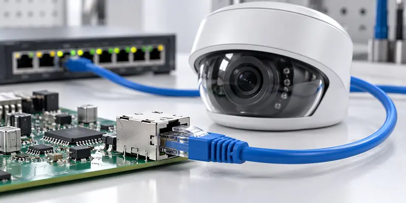
An IP camera transmits encoded video at a bitrate, not at its image resolution expressed in pixels. Load changes with codec, frame rate, compression, scene complexity, image noise, key-frame interval, analytics, audio, metadata, and simultaneous streams. Movement, rain, foliage, noise, or frequent I-frames can increase a variable-bitrate stream. Axis guidance likewise notes that scene complexity can cause bitrate to jump and insufficient infrastructure can produce packet loss or stopped streams.
For that reason, do not decide from “4 MP,” “8 MP,” or “4K” alone. Obtain the camera manufacturer’s maximum configured bitrate or measure a worst-case test configuration. Add the main stream, substream, audio, metadata, and any concurrent consumers. Then compare the result with the usable capacity of the complete path, not merely the port’s nominal link rate.
A useful engineering expression is:
Required path bandwidth = sum of the maximum configured bitrates of all simultaneous streams + protocol and operational headroom
There is no universal headroom percentage. Variable bitrate, failover, remote viewing, multicast design, and the cost of dropped frames differ by project. Define the margin and validate it under representative motion, lighting, analytics, and client-access conditions.
Fast Ethernet remains technically defensible for a single camera when this worst-case total stays well inside the design limit and the product has no expansion requirement. Gigabit becomes the better choice when the same port must support multiple sensors, several high-bitrate streams, intensive analytics, large image bursts, or future firmware features whose traffic is not yet fixed.
NVR Uplink Design With a 1G RJ45 Connector
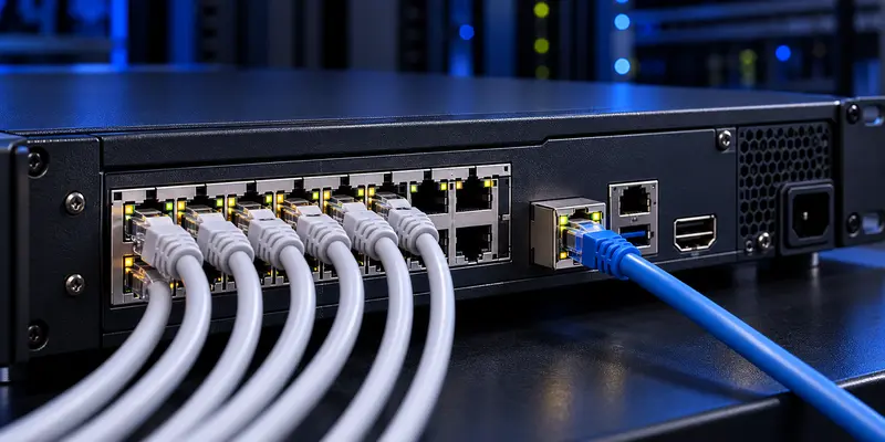
NVR sizing is an aggregation problem. If 16 cameras are configured at a maximum of 8 Mbps each, their video contribution is already 128 Mbps before overhead, playback, remote users, backups, or failover traffic. This example illustrates the calculation; it does not prescribe a universal camera bitrate.
Use project inputs rather than a camera-count shortcut. Add the maximum bitrate of every stream expected to cross the same NVR or switch uplink, identify which streams can occur at the same time, and include non-video traffic. This calculation often supports a 1G RJ45 port for NVR LAN connections and central switch uplinks even when individual camera ports operate at 100 Mbps.
The link rate is only one NVR limit. Manufacturers may specify incoming bandwidth, outgoing bandwidth, decoding capacity, storage throughput, and channel count separately. A physical gigabit port does not prove 1 Gbps video ingest. For models with built-in PoE ports, also separate the internal camera network from the LAN/uplink and document each port as PD, PSE, or data-only.
PoE Magnetic RJ45 Connector Requirements for Camera and NVR Ports
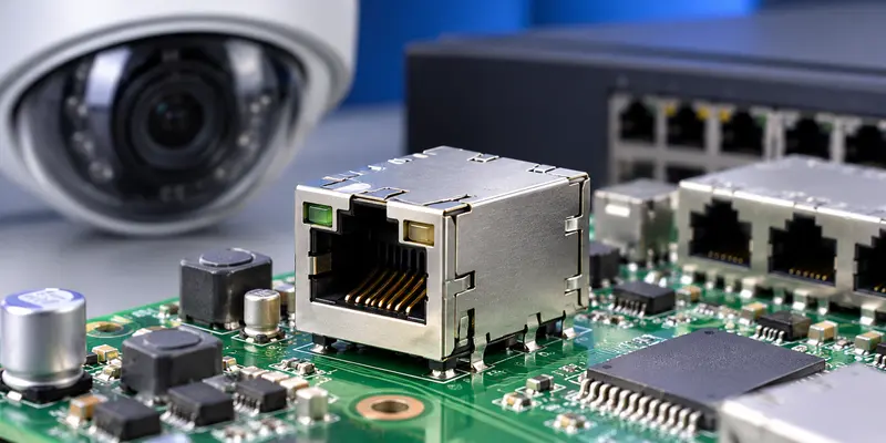
Ethernet speed and PoE capability are separate decisions. A camera is normally a powered device, while a PoE NVR or switch is power sourcing equipment. The magnetic RJ45 connector supplies the modular interface and Ethernet isolation components, but the system still needs the appropriate PD or PSE controller, power path, protection, and conversion circuitry.
For a Gigabit PoE port, confirm that the integrated magnetics support 1000BASE-T and that the center taps and pinout match the PHY and PoE controller architecture. Review current rating, contact resistance, transformer winding, temperature rise, insulation, shield connection, and the worst-case enclosure temperature. A multi-port NVR or switch deserves bank-level thermal analysis because several powered ports can operate simultaneously in limited front-panel and PCB space.
Calculate power from worst-case behavior, not daytime average consumption. Infrared illumination, heaters, wipers, pan-tilt-zoom motors, startup, and accessories may overlap. On the PSE side, verify both per-port demand and total system power. GLGNET’s PoE MagJack selection guide covers this power-path decision in greater detail.
Does It Matter What RJ45 Connector I Use?
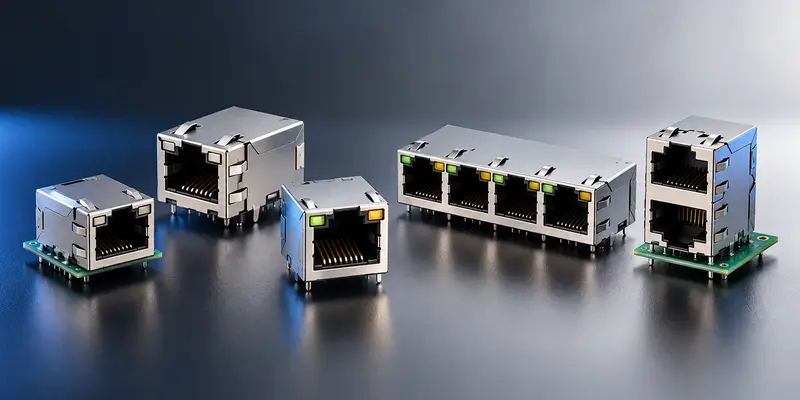
Yes. An RJ45 connector is not qualified merely because the plug fits. Two board-mount jacks can differ in supported data rate, number and topology of magnetic channels, return loss, insertion loss, common-mode rejection, isolation, center-tap access, PoE current path, shield design, LED wiring, footprint, mounting method, solder process, and operating temperature.
First decide whether the product needs a standard RJ45 jack connector with discrete magnetics or an integrated RJ45 with magnetics. Discrete parts offer layout flexibility; an integrated module can reduce external components. In both cases, the schematic, pins, and footprint must match the PHY reference design. Similar front faces do not prove drop-in compatibility.
Then verify shield and chassis strategy, LED circuits, footprint, mounting, solder process, temperature, and enclosure conditions. Also distinguish the PCB component from the field cable plug: GLGNET’s RJ45 jacks are host-board parts, while cable category, termination, jacket, bend radius, and installation workmanship belong to the channel design.
Security Ethernet Connector Selection Examples
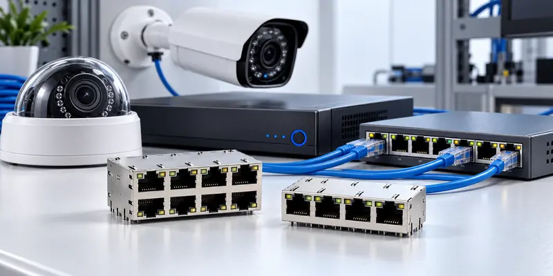
A compact fixed camera with validated peak traffic well below the project limit can use a correctly specified 10/100 magnetic module. A multi-sensor camera serving several streams, analytics data, and concurrent clients may justify four-channel 1000BASE-T at the edge. For an NVR, compare calculated simultaneous traffic with its published incoming, outgoing, and processing limits before selecting the LAN/uplink rate.
For a PoE NVR or switch, evaluate data and power together. The uplink may need Gigabit for aggregation while camera-facing ports use Fast Ethernet or Gigabit by design. Every powered port must also meet its PD/PSE role, current, protection, and thermal requirements. GLGNET’s security Ethernet connector solutions page shows how RJ45 and optical interfaces fit into surveillance equipment.
1000BASE-T RJ45 Checklist for IP Cameras and NVRs
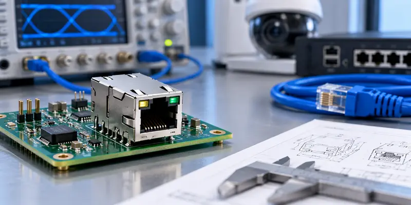
Before releasing an RFQ, identify the application and port role; PHY; data rate; magnetic schematic and electrical limits; PoE PD, PSE, or data-only function; worst-case power and temperature; port count and orientation; PCB footprint; shield strategy; LEDs; mounting process; operating environment; compliance targets; and validation plan.
Validation should cover auto-negotiation, interoperability, signal integrity, worst-case video traffic, high-load PoE operation, temperature rise, required ESD or surge behavior, and production robustness. Test ganged NVR ports with realistic simultaneous traffic and power rather than qualifying one port in isolation.
GLGNET lists integrated magnetic options from 10/100M through 1G and higher rates, with several arrangements, orientations, LED options, and mounting methods. Its company materials describe signal-integrity simulation, testing, debug, test-board design, and electrical test resources. Final approval must still use the exact drawing, internal schematic, datasheet, PHY reference design, and system tests. Engineers can review the Magnetic RJ45 connector range or provide project inputs for a part-level recommendation.
RJ45 Connector FAQ for IP Camera and NVR Systems
Do IP cameras need Gigabit Ethernet?
Not all IP cameras need Gigabit Ethernet. A fixed camera with one or two controlled video streams can operate reliably through Fast Ethernet when its maximum configured traffic, protocol overhead, and engineering margin remain comfortably inside the 100 Mbps path. The decision should use the camera datasheet or a worst-case traffic test rather than resolution alone, because codec, frame rate, scene activity, image noise, analytics, audio, metadata, and the number of simultaneous clients all affect bitrate. A 1000BASE-T RJ45 interface becomes more appropriate for multi-sensor cameras, several high-quality streams, intensive edge analytics, multiple concurrent viewers, or a product roadmap that may increase traffic after launch. The PHY must support the intended rate, and the host-board magnetics, routing, and cable channel must be designed for the same standard. Upgrading only the modular connector cannot turn a 10/100 PHY into a 1 Gbps interface. Select the complete Ethernet channel from verified traffic and architecture requirements.
Is 100 Mbps enough for an IP camera?
Yes, 100 Mbps can be enough for an individual IP camera, but only after the traffic budget is calculated. Add the maximum configured bitrate of every stream that can operate at the same time, including the recording stream, live-view substream, audio, analytics metadata, and any additional client sessions. Allow for protocol overhead and variable-bitrate peaks caused by movement, detailed backgrounds, rain, low-light image noise, or frequent key frames. The result should remain comfortably below the usable capacity defined by the project, not merely below the nominal 100 Mbps link rate. Validation should reproduce representative night operation, motion, analytics, and remote viewing rather than relying on an idle daytime scene. This conclusion applies only to that camera connection. Ten or twenty individually acceptable Fast Ethernet cameras may still overload a 100 Mbps switch or NVR uplink when their traffic is aggregated. The edge-port and uplink RJ45 jacks therefore need separate calculations in practice.
Do NVRs need Gigabit ports?
Many new NVR designs benefit from a Gigabit port because the LAN interface aggregates multiple camera streams and may simultaneously carry live view, playback, export, management, backup, and remote-access traffic. Begin with the maximum configured bitrate of every stream expected to cross the port at the same time, then include protocol overhead and an operating margin appropriate to the project. Compare that total with the Ethernet link rate and with the recorder manufacturer’s separate limits for incoming or recording bandwidth, outgoing bandwidth, decoding capacity, channel count, and storage throughput. These values are not interchangeable. A recorder can have a physical 1 Gbps interface while its processor or storage subsystem supports a much lower video ingest rate. For an NVR with integrated PoE camera ports, also distinguish the internal camera network from the external LAN or uplink. The correct RJ45 modular jack connector decision follows the traffic path and recorder specification, not the number printed beside the port.
What Ethernet cable is best for a security camera system?
Use a standards-compliant structured cabling channel that supports the required Ethernet rate, PoE load, route length, and installation environment. Cat5e can support 1000BASE-T when the complete channel is correctly specified and installed. Cat6 is a common choice for new camera networks because it provides additional transmission margin and leaves more flexibility for future equipment changes. Cable category alone is not enough in practice. Check solid or stranded conductor use, conductor gauge, outdoor or UV exposure, plenum or fire-rating requirements, shielding and bonding, temperature, water ingress, bend radius, patch length, and local installation codes. For PoE, the cable and terminations must also handle the expected current and heat, especially in large bundles. The complete channel includes cable, field plugs, patch cords, wall jacks or panels, and the equipment RJ45 jack connector. A higher-category cable cannot compensate for poor termination, damaged pairs, an incompatible component, or a host board that supports only Fast Ethernet.
Can a 1G RJ45 port work at Fast Ethernet speed?
Often yes, provided the PHY and the complete product design support 10/100/1000 auto-negotiation. A Gigabit-capable host port can normally establish a 100 Mbps link with compatible equipment, but the label on the connector is not enough to prove this behavior. Confirm the PHY feature set, strap and firmware configuration, transformer schematic, pinout, center-tap arrangement, termination network, and the rates covered by product validation. The cable channel must also preserve the pairs required by the negotiated mode. A common mistake is to treat an RJ45 with magnetics component as the part that determines speed. It does not. The operating rate results from the PHY, magnetics, PCB routing, connector, cable, link partner, and negotiation settings working together. Installing a four-channel 1000BASE-T magnetic module on a board with a 10/100 PHY will not create a 1 Gbps interface. Likewise, a compatible connector cannot correct disabled auto-negotiation or an incorrect reference circuit during qualification.
What is the fastest Ethernet connection for IP surveillance?
Ethernet standards extend far beyond 1 Gbps, but the fastest available interface is rarely the correct target for an ordinary camera endpoint. The right speed is the lowest architecture that carries the verified simultaneous traffic with the required margin, reliability, reach, power design, and cost. Fast Ethernet can remain suitable for controlled single-camera RJ45 jacks, while 1 Gbps is commonly justified for NVR LAN ports, PoE switch uplinks, multi-sensor cameras, and expandable surveillance systems. Multi-gigabit copper or optical links may be appropriate at core aggregation points, between buildings, over long distances, or in large recording architectures where several Gigabit links converge. Those backbone requirements should not be projected automatically onto every camera. Evaluate the complete traffic path, redundancy plan, switch fabric, recorder limits, cable reach, and environmental conditions. Selecting excessive port speed without a matching PHY, PCB, thermal design, or network requirement increases complexity without necessarily improving recorded image quality.
Choose the Right RJ45 Jack Connector With GLGNET
Choose Fast Ethernet only after verifying the complete single-port traffic budget and product roadmap. Choose Gigabit for aggregation points and camera ports whose simultaneous traffic, variability, or expansion needs make 100 Mbps restrictive. In either case, qualify the connector as part of the PHY, magnetics, PoE, PCB, enclosure, and cable channel—not as a standalone mechanical part.
For a focused recommendation, send GLGNET the camera or NVR port role, PHY part number, required Ethernet rate, maximum stream traffic, PoE type and load, port count, schematic or reference part, footprint, LEDs, shield requirement, mounting process, operating temperature, and compliance targets. This gives the engineering team enough information to compare an RJ45 modular jack connector or integrated MagJack at the part level rather than guessing from a catalog photo.
For related connector selection guidance, review the PoE magnetic RJ45 connector guide for surveillance and access networks, the 2.5G vs 5G vs 10GBASE-T MagJack selection guide, the MagJack cross-reference guide, the data center connector selection guide, the industrial Ethernet connector guide, the SFP port connector selection guide, and the high speed connector performance guide for AI data centers. Browse GLGNET’s magnetic RJ45 connector portfolio or explore networking connectivity solutions for more.