Select an industrial ethernet connector by first defining where the port will operate, then matching the Ethernet rate, PHY and magnetics, PoE requirement, shielding, PCB mounting, front-panel geometry, and qualification conditions. For a switch or gateway inside a protected cabinet, a PCB-mounted RJ45 may be appropriate. A port exposed directly to washdown, dust, chemicals, or continuous vibration may require a sealed, locking field interface instead.
What Is an Industrial Ethernet Connector for Switches and Gateways?
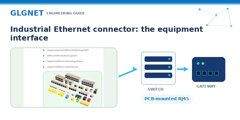
An industrial ethernet connector is not identified by one universal shape. It is the physical interface selected and qualified to carry Ethernet reliably under the electrical, mechanical, environmental, and lifecycle conditions of industrial equipment. The underlying Ethernet communication can be familiar, but the hardware has to tolerate conditions that office networking rarely sees: wider temperature changes, electrical noise, repeated vibration, restricted enclosure space, long service periods, and production processes that must remain consistent across many units.
For switch and gateway designers, the word connector can refer to two different boundaries. The first is the external interface that a technician mates in the field. The second is the device-side component mounted on the PCB, such as a standard RJ45 jack or a magnetic rj45 connector with integrated transformers and filtering. These boundaries affect different decisions. An IP-rated cable connector cannot compensate for a poorly grounded board-level jack, and a well-designed PCB connector does not make an unsealed enclosure suitable for direct washdown.
That distinction is essential for procurement. Before requesting an “industrial” part, state whether the connector sits inside a sealed cabinet, behind a protected front panel, or on a machine where it is directly exposed. The correct specification begins with the installation boundary, not with a generic product label.
Industrial Ethernet Connectors at the Equipment Side and Field Side
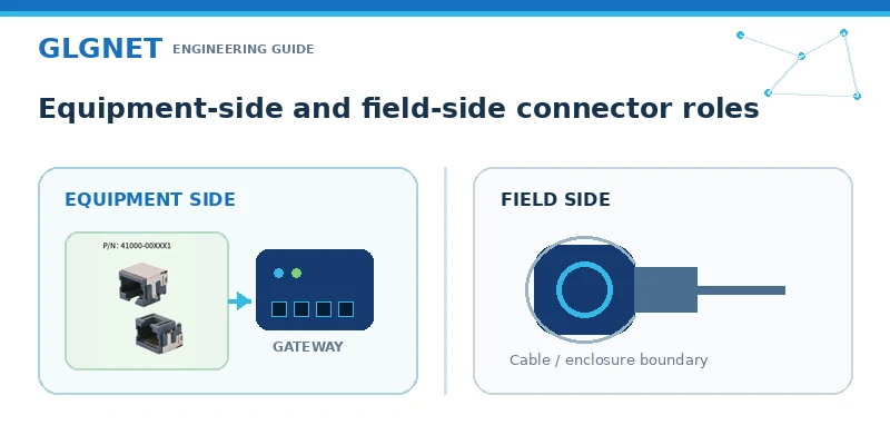
Industrial Ethernet systems commonly use RJ45, M8/M12, ix Industrial, or fiber, but these interfaces solve different installation problems. RJ45 is widely used on switches, gateways, controllers, and management ports because it is compact, familiar, and compatible with a broad installed base. M8 and M12 circular interfaces are commonly considered when a mated connection needs stronger locking and environmental sealing. ix Industrial addresses compact equipment that requires a standardized, mechanically secure interface. Fiber becomes relevant when reach, galvanic separation, or severe electromagnetic conditions make copper less suitable.
GLGNET supports the equipment-side RJ45 architecture used in switches, gateways, controllers, and related network hardware. When a system uses M12 or another sealed field connector, engineers should evaluate the exposed interface and the internal Ethernet circuit as separate design boundaries. The sealed connector, cable system, enclosure, PCB interface, PHY, and magnetics must work together, but each part requires its own compatibility and qualification evidence.
| Installation condition | Interface direction to evaluate | What must be confirmed |
|---|---|---|
| Protected control cabinet or indoor enclosure | PCB-mounted RJ45 or Magnetic RJ45 | Rate, PHY, magnetics, shield, mounting, panel fit, LEDs |
| Exposed machine or outdoor port | Sealed locking field interface | Mated IP rating, materials, chemicals, vibration, cable system |
| Compact high-density device | RJ45 if space permits; compact standardized alternative if required | Port pitch, connector height, retention, service access |
| High-EMI or longer-reach link | Shielded copper system or fiber, based on the link design | Grounding, cable, transceiver/interface compatibility, system test |
Selection framework only; it is not a GLGNET product specification. Final compatibility and environmental ratings must be verified against the exact part number and complete system design.
Choose an Industrial RJ45 Connector by Speed, PHY, and Port Role
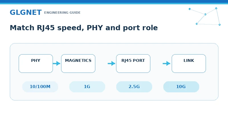
Once RJ45 is confirmed as the correct equipment-side interface, define the port role before selecting the part. A maintenance or management port may have a different rate and duty profile from a multiport access switch. A gateway may need one or two Ethernet ports with limited board area, while a switch may need ganged or stacked ports and consistent LED visibility across the front panel. The same mechanical opening does not guarantee electrical compatibility.
Match the industrial rj45 connector to the Ethernet standard and the PHY design. A 10/100 interface, a gigabit rj45 connector, and a multigigabit or 10GBASE-T interface do not impose the same magnetics, insertion-loss, return-loss, crosstalk, or PCB-layout requirements. The PHY vendor’s reference design and approved magnetics guidance should be treated as design inputs. Procurement should request the connector schematic, pin assignment, transformer ratios where applicable, common-mode choke configuration, center taps, LED circuit, and electrical performance data instead of relying only on a speed label.
The board architecture then determines whether to use a standard jack with separate LAN magnetics or an integrated connector module. A standard RJ45 jack can give the engineer more freedom to choose and place external magnetics, but it consumes additional board area and creates more layout interfaces to control. An integrated solution combines the jack and magnetic functions, reducing separate components and simplifying the path from the PHY to the line side. Neither architecture is automatically better; the correct choice is the one validated with the selected PHY, PCB stack-up, compliance targets, and manufacturing process.
Select a Magnetic RJ45 Connector for PoE, Isolation, and EMI
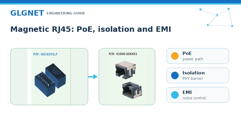
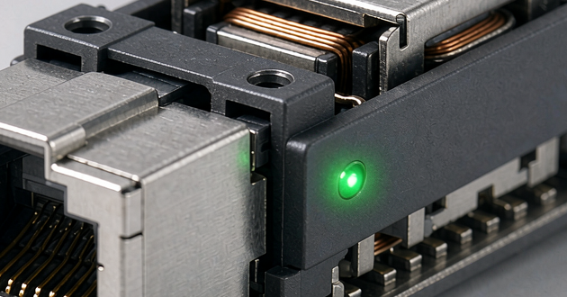
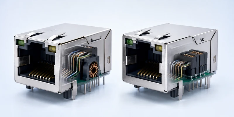
A magnetic rj45 connector can be useful in compact switches and gateways because it integrates the modular jack with Ethernet magnetics. Those magnetics provide the transformer isolation and common-mode behavior required by the chosen Ethernet interface. Integration can reduce component count and simplify layout, but it also makes exact circuit compatibility more important. Two parts with the same outline may have different pinouts, center-tap arrangements, LED circuits, magnetics, or PoE current paths.
For PoE ports, data rate alone is not enough. The engineer must identify whether the equipment is power sourcing equipment, a powered device, or a non-PoE data port; confirm the applicable IEEE 802.3 PoE implementation; and calculate current, loss, and temperature rise for the actual number of powered pairs and simultaneously loaded ports. A connector family may include high-power options, but that does not mean every part number supports the same power. Ambient temperature, adjacent-port loading, copper area, airflow, contact resistance, and the magnetics design all influence the result.
Shielding also has to be treated as a path rather than a checkbox. The metal shell, ground tabs, chassis connection, cable shield, front-panel contact, and PCB return strategy must work together. A shielded connector installed with poor chassis bonding can still perform badly in an emissions or immunity test. Use the supplier drawing and recommended grounding approach, then verify the finished switch or gateway at system level. GLGNET offers Magnetic RJ45 options covering 10/100M through 10G and PoE configurations, including designs described as supporting up to 150W, but the required performance must be confirmed for the exact part and application.
Match Industrial Ethernet Connectors to PCB and Front Panel Design
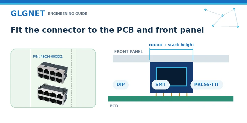
Mechanical integration often eliminates more candidates than the data-rate filter. Industrial ethernet connectors for equipment boards must match the connector orientation, port height, board edge, enclosure cutout, LED position, retention features, and the space needed for mating and cable release. A technically compatible jack can still create an unusable product if the latch cannot be reached, the plug interferes with an adjacent port, or the LED light path is hidden by the bezel.
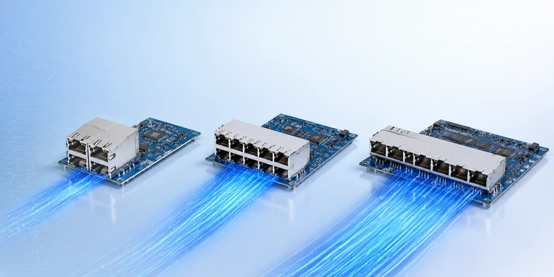
Mounting method must also fit the manufacturing plan. DIP through-hole, SMT, press-fit, pin-in-paste, right-angle, vertical, single-port, ganged, and stacked designs serve different board and assembly needs. High-port-count switches may favor arrays that reduce placement steps and maintain a consistent front-panel pattern. Compact gateways may prioritize height, depth, and a clean relationship between the connector body and enclosure. The choice should be reviewed by electrical, mechanical, and manufacturing teams before the PCB footprint and tooling are frozen.
Do not approve a replacement part from a marketing cross-reference alone. Compare the dimensioned drawing, keep-outs, pin grid, shield tabs, polarity, LED circuit, pinout, mating geometry, coplanarity or press-fit requirements, materials, and process limits. A sample should be checked in the intended PCB and enclosure, not only mated on a bench.
Validate an Industrial Ethernet Connector for the Operating Environment
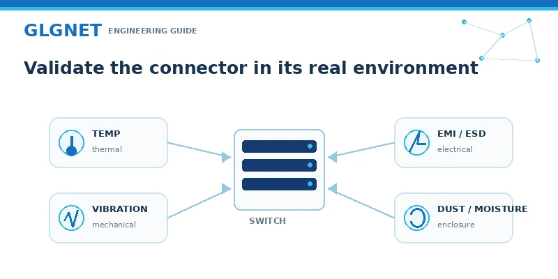
Environmental selection should translate the real installation into measurable acceptance criteria. “Factory use” is too vague. A gateway inside a climate-controlled cabinet and a switch mounted near a motor drive are both industrial products, yet their thermal, contamination, vibration, grounding, and service conditions can be completely different. The industrial ethernet connector must be evaluated as part of the complete port, including cable, enclosure, PCB, PHY, magnetics, protection components, and power path.
Temperature qualification should include the equipment’s worst-case internal ambient, not only the room temperature. Vibration and shock reviews should consider connector retention, solder or press-fit joints, cable movement, and front-panel support. For dust, moisture, oil, or chemicals, verify the mated enclosure and materials rather than assuming a shielded RJ45 is sealed. EMC work should include emissions, immunity, ESD, surge requirements where applicable, and the grounding architecture of the finished equipment.
| Validation area | Evidence to request or generate | Failure the check is intended to prevent |
|---|---|---|
| Electrical | Schematic, PHY compatibility, magnetics data, SI and compliance results | Link instability, packet errors, failed interoperability |
| PoE and thermal | Current path, contact resistance, port loading, temperature-rise test | Overheating, power loss, reduced long-term margin |
| EMC and protection | Shield/ground plan, ESD and emissions/immunity test plan | Interference, resets, regulatory failure |
| Mechanical and environment | Drawing, enclosure fit, vibration, temperature and exposure criteria | Intermittent contact, damage, seal or service failure |
| Manufacturing and lifecycle | Assembly window, inspection, traceability, change control and supply plan | Yield variation, undocumented substitutions, redesign risk |
The required tests depend on the device, market, installation and exact part. The table is a validation framework, not a claim that every GLGNET connector carries every listed rating.
Industrial Ethernet Connector RFQ Checklist for OEM Hardware
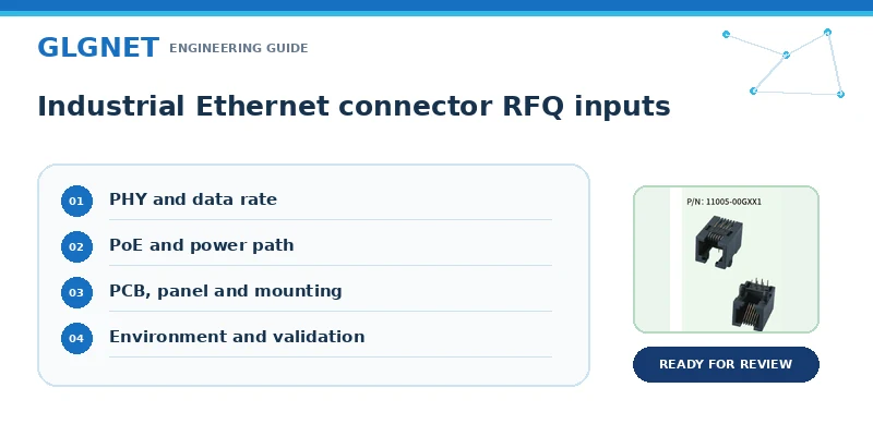
A useful RFQ lets the ethernet connector manufacturer evaluate electrical and mechanical compatibility before samples are ordered. Start with the device and port role, then attach the PHY information and current schematic. Add the target Ethernet rate, PoE role and power requirement, PCB mounting process, port count and arrangement, enclosure drawing, LED preference, shield and grounding concept, operating environment, required standards, annual volume, qualification schedule, and any reference part that is being replaced.
| RFQ input | Minimum information to provide |
|---|---|
| Electrical architecture | Ethernet rate, PHY, standard jack or integrated magnetics, pinout, PoE role |
| Mechanical design | Orientation, height/depth limits, 1xN or 2xN layout, PCB and panel drawings |
| Environment and compliance | Temperature, vibration, contamination, EMC/ESD and market requirements |
| Production plan | Mounting process, inspection needs, sample quantity, forecast, lifecycle and change control |
GLGNET’s Networking connectivity solutions cover RJ45, Magnetic RJ45, and other networking interfaces for switches, routers, gateways, and related equipment. For a board-level Ethernet design, review the available Magnetic RJ45 connectors when integrated magnetics, PoE, shielding, LEDs, or compact port structures are required, or compare PCB-mount RJ45 jacks when the design uses separate LAN magnetics. Supplying complete inputs early helps an ethernet connector supplier recommend a realistic sample instead of a visually similar but electrically incompatible part.
Industrial Ethernet Connector FAQ
What is the difference between Ethernet and industrial Ethernet?
Industrial Ethernet uses Ethernet technology in systems designed for industrial operating conditions. The connector, cable, enclosure, grounding, temperature range, EMC design, vibration resistance, and lifecycle controls are selected for the actual installation rather than an office environment.
Can RJ45 be used for industrial Ethernet?
Yes. RJ45 is common in protected cabinets and equipment ports. If the mated interface is directly exposed to liquids, dust, chemicals, or severe vibration, a sealed locking interface or protected enclosure may be more appropriate.
Should I use T568A or T568B for a switch or gateway?
T568A and T568B describe twisted-pair cable termination. They do not replace the PCB jack, magnetics, PHY, or pinout review. Use the project’s cabling standard consistently and verify the device-side schematic separately.
What cable is best for an industrial Ethernet application?
Choose cable by rate, distance, flexing, temperature, oil or chemical exposure, flame requirement, shielding, and installation rules. The connector and cable must form a compatible system; a rugged cable cannot correct an unsuitable connector or grounding design.
When should a gateway use a gigabit RJ45 connector?
Use a gigabit rj45 connector when the PHY, traffic, uplink, and product roadmap require 1000BASE-T. Confirm magnetics and layout compatibility; choosing Gigabit only as a label adds no value if the rest of the port is designed for another rate.
Choose the Right Industrial Ethernet Connector with GLGNET
The right industrial ethernet connector is the one that matches the complete switch or gateway, not just the cable plug. Define the installation boundary, rate, PHY, magnetics, PoE, shield path, PCB process, front panel, operating conditions, and qualification plan before freezing the part number. This approach reduces redesign risk and gives engineering and purchasing teams a shared basis for supplier comparison.
GLGNET provides standard RJ45 jacks and Magnetic RJ45 connector options for networking equipment, with choices for different rates, mounting methods, port structures, shielding, LEDs, pinouts, and PoE designs. Contact GLGNET with your PHY, schematic, PCB or panel drawing, reference part number, target environment, and production plan to evaluate a suitable connector for prototype verification.
For higher-speed board designs, also review the 2.5G vs 5G vs 10GBASE-T MagJack selection guide or the MagJack cross-reference guide for replacement and qualification support. If your design also uses front-panel high-speed links, see the data center connector selection guide for AI servers and network switches.