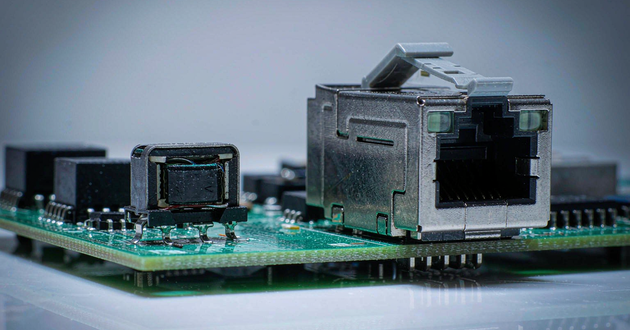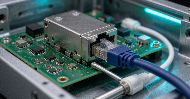
Choose magnetic RJ45 mounting types together with the PCB fabrication requirements and assembly sequence. A connector can fit the enclosure and satisfy the Ethernet circuit yet require a process the factory has not planned. Through-hole construction does not automatically exclude reflow, and a soldering temperature printed on a drawing does not establish full reflow compatibility.
For OEM buyers, the useful decision is whether the exact connector, board and production route work together. Establish the termination method for every contact and shield leg, obtain the part-specific processing limits, then confirm placement, inspection and rework with the assembler. This guide explains how to turn those checks into an actionable sample request.
Separate Magnetic RJ45 Mounting Types from Soldering Processes
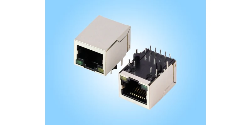
Through-hole, surface-mount and press-fit describe how terminals connect to the board. Wave soldering and reflow describe production processes. Pin-in-paste, also called paste-in-hole or through-hole reflow, is a way to solder suitable through-hole components using paste and a reflow process. These terms answer different questions and should occupy separate fields in a supplier comparison.
IRISO's board-mounting guide distinguishes these structures and explains why specially specified through-hole products can enter a reflow route. GLGNET's company profile, page 20, and catalogue PDF page 23 describe through-hole, SMT and press-fit options at portfolio level. They do not identify every currently orderable variant or approve a specific production profile.
| Terminal construction | Board connection | Processing information to obtain |
|---|---|---|
| Soldered through-hole, often labelled DIP | Leads enter plated holes | Approved soldering route, lead geometry and board requirements |
| Surface-mount, or SMT | Solder tails meet surface pads | Land pattern, coplanarity, paste and reflow requirements |
| Press-fit | Specified press-in terminals engage plated holes | Hole specification, board limits, tooling and insertion requirements |
| Through-hole suitable for pin-in-paste | Through-hole leads are soldered during reflow | Explicit part approval, stencil/paste requirements and thermal profile |
Do not compare “DIP versus reflow” as if they were competing connector structures. Instead ask, “Which through-hole part is approved for our intended process?” That distinction can prevent ordering a mechanically correct component that still requires an unplanned soldering operation.
When a Through-Hole RJ45 MagJack Fits the Production Line
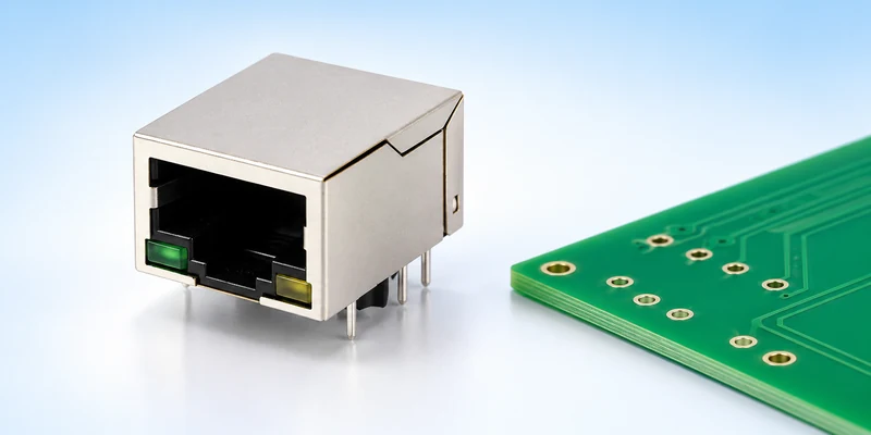
A through-hole RJ45 MagJack needs more than matching hole centres. Check lead dimensions and protrusion against finished board thickness, confirm the specified hole tolerances, and identify positioning posts and shield stakes separately from electrical terminals. A footprint transferred from a similar-looking jack is insufficient evidence of compatibility.
GLGNET's JLFA1S805-G/YP product page identifies a through-hole magnetic RJ45 configuration. Its 130005-06811 drawing provides a component-side PCB layout and separately depicts the terminal, mounting and shield features. Preserve the drawing's viewing direction when creating the library footprint. Mirroring the pattern incorrectly can leave a board that looks plausible in CAD but cannot accept the part.
Evaluate the tolerance combination as well as the nominal dimensions. At the allowed board-thickness extremes, the supplier and assembler should confirm that the terminal engagement and protrusion remain suitable for the chosen soldering route. Keep connector seating height and any specified standoff in the assembly review. A board that can accept the pins mechanically can still need a different process arrangement if the seating condition, support or available soldering access changes. Resolve those relationships before treating an existing footprint as reusable.
Review the underside with the assembler. Components, fixtures and board supports must leave the intended soldering locations accessible. Connector height and proximity to other parts can also affect handling and the process arrangement. Establish these constraints using the actual assembly drawing rather than a general statement that through-hole connectors are always stronger or cheaper.
If the remaining PCB is reflow assembled, identify when the jack enters production. A wave-soldered connector may be fitted in a subsequent operation; a specifically approved through-hole reflow part may follow another route. Whether either option reduces work depends on the existing line, board design, volume and inspection needs. Ask the contract manufacturer to quote the complete route, including setup and any connector-specific tooling.
Can This RJ45 Connector Pass Through Reflow?
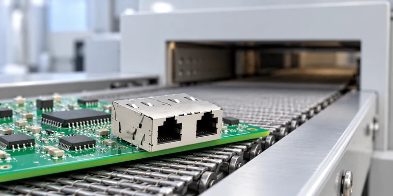
The request for a reflow compatible RJ45 connector must be answered with a specification for the exact part. On page 1 of GLGNET file 130005-06811, the recommendation is wave soldering, with a peak soldering temperature of 260°C maximum for 10 seconds maximum. That statement is not a complete reflow profile and does not independently approve passing this connector through a reflow oven.
There is a different, explicitly documented GLGNET example. File 130067-00111, page 2, names wave soldering or through-hole reflow and lists a peak soldering temperature of 265 ± 5°C for 10 seconds. The drawing identifies JGRBPG2T1034PW, whereas its linked webpage uses JGRPG2T1034PW. Resolve that ordering-code difference before using the document to approve a process. Its note also does not supply every stage or allowed cycle of a production profile.
TE's industrial magnetic-jack range separately specifies 260°C pin-in-paste reflow capability. This illustrates the kind of explicit process designation to seek; TE's capability is not a GLGNET specification.
Request the supplier's applicable time–temperature profile, measurement locations, permitted process cycles and preparation or handling instructions. Compare those requirements with the actual board process, including any second pass and planned rework. Ask whether auxiliary parts, such as LEDs or a placement cap, introduce additional limits. Do not infer whole-assembly capability from the housing resin alone.
Pin-in-paste also needs sufficient solder and access around the leads. Samtec's processing guide explains why material suitability, lead clearance, board thickness and stencil design must be considered together. The thermal designation is therefore necessary information, but it does not replace the PCB and paste-volume review. Use the selected supplier's dimensions rather than copying another connector's stencil aperture.
Through Hole vs SMT RJ45: What Changes with Press-Fit Assembly?
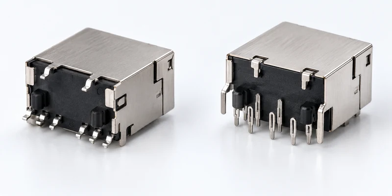
The through hole vs SMT RJ45 decision changes the PCB connection and manufacturing inputs. With SMT, the pad pattern and terminal coplanarity matter because solder tails must meet the board surface as intended. Confirm the approved land pattern, solder-mask and paste recommendations, placement method and inspection access. Check whether the package supplies a suitable pickup surface or cap and whether the requested packaging suits the placement equipment.
For a press fit magnetic RJ45 proposal, obtain the connector manufacturer's finished-hole specification and the relevant board construction limits. A soldered through-hole footprint should not simply be reused. Hole size, tolerance, plating and board thickness must suit the proposed contact system. Coordinate the specification with the PCB fabricator and assembler before ordering either boards or connector samples.
IRISO's mounting guide describes press-fit assembly as a controlled pressing operation using suitable tooling. Review insertion direction, the area where force may be applied, board support and access for the tool. Adjacent parts must not prevent the agreed operation. Request applicable insertion and retention criteria rather than choosing a force from a different press-fit product.
Press-fit removes soldering at the specified press-fit connection, but it does not remove assembly planning. The factory still needs the correct equipment, support, monitoring and inspection. Similarly, SMT does not mean that every metal feature of an RJ45 assembly is surface soldered. Check the complete drawing before deciding that one process covers the whole part.
Review Every Magnetic RJ45 Connector Terminal and Shield Tab
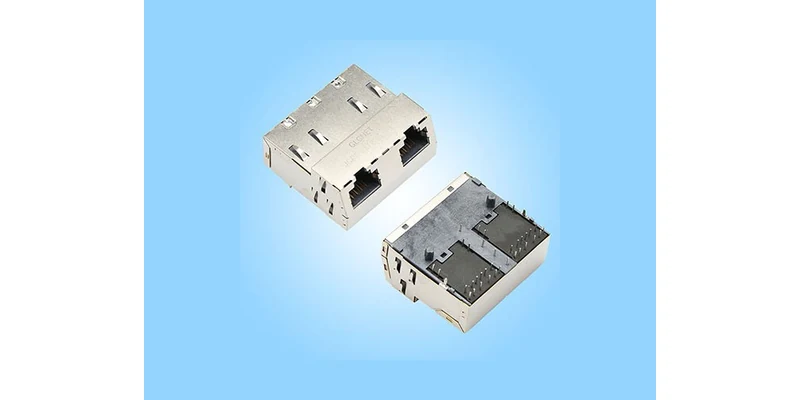
A magnetic RJ45 connector may include signal terminals, LED terminals, shield connections and non-electrical locating features. Record what each feature does and how it is attached. A front product photograph cannot establish the full termination pattern, and the shape of a large metal leg does not by itself establish whether it is soldered, press-fitted or used only for retention.
Compare the mechanical views, recommended PCB layout and electrical schematic together. For the JLFA1S805-G/YP example, the drawing includes separate LED connections and shield-related mechanical features in addition to the magnetic circuit terminals. Confirm every required hole or pad against its function. Keep electrical isolation and intended shield grounding consistent with the approved design; an assembly convenience should not silently alter that circuit.
Where different terminal groups need different operations, write the sequence explicitly. Establish which parts are installed before each heating or pressing step, what needs protection or support, and how completed connections remain accessible for inspection. This is especially important when changing an existing connector: matching the front-panel opening does not establish a matching assembly route.
Define how a failed part will be replaced. The assembler needs access, approved tools and applicable thermal or mechanical limits for removal and replacement. Do not assume that a successful first installation proves a practical rework route. Include the consequences for nearby components and the PCB when comparing the complete cost of two otherwise suitable candidates.
Match the RJ45 Connector Supplier's Proposal to Your Process
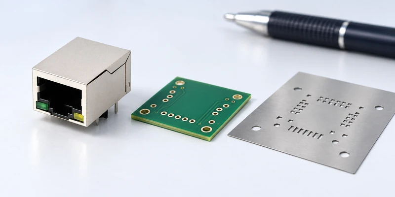
Give the RJ45 connector supplier a concise manufacturing package before requesting samples. The objective is a specific part and process proposal that engineering and the assembler can review against the same inputs.
| Input to provide | Decision it enables |
|---|---|
| Proposed connector and controlled drawing revision | Confirms the exact construction and options |
| PCB thickness, hole or pad files and fabrication tolerances | Checks terminal fit and board compatibility |
| Assembly sequence and available equipment | Identifies soldering, placement or pressing operations |
| Actual thermal profile and expected process cycles | Compares the intended exposure with part-specific approval |
| Panel, adjacent components and underside access | Reviews handling, support, tooling and inspection |
| Acceptance and rework requirements | Defines how installation and replacement will be evaluated |
| Prototype quantity and production milestones | Supports a configuration and supply discussion without assuming availability |
Ask for a written response identifying approved inputs, exceptions and missing information. A sample should have the same termination construction and relevant options as the quoted production configuration. If the supplier proposes a different mounting style, revisit the PCB and process instead of treating it as a purchasing-only substitution.
Separate sample handling from production handling in that response. Hand-placing a prototype does not confirm how an automatic line will grip and present the part. Obtain the proposed tray or tape-and-reel arrangement, connector orientation and pickup method where relevant. Ask the assembler to identify any required placement cap or dedicated support fixture in its quotation. These are concrete manufacturing inputs that can explain why two electrically equivalent proposals have different assembly requirements, without assuming a particular cost saving or cycle-time improvement.
Use a first-article assembly to check the agreed installation and inspection method before releasing a production build. Record the connector identity, board revision, process used and results required by the OEM's acceptance plan. A working Ethernet link is useful functional information; it does not document every solder joint or press-fit connection.
For broader dimensional and electrical inputs, use GLGNET's custom connector design checklist. Send the board thickness, hole/pad drawing, assembly sequence and thermal profile when requesting an installation-process and model review. GLGNET's magnetic RJ45 range and engineering services provide the next route for discussing the required configuration; portfolio descriptions should still be confirmed against the specific proposed part.
Magnetic RJ45 Mounting Types FAQs
Does a 260°C soldering limit prove full reflow compatibility?
No. The process named in the specification matters. A wave-soldering peak and duration do not supply a complete reflow approval. Obtain the exact part's applicable profile, permitted cycles and handling requirements, then compare them with the actual production process.
Is pin-in-paste the same as an SMT connector?
No. Pin-in-paste uses suitable through-hole leads and plated holes, with solder paste processed during reflow. An SMT termination meets surface pads. Both can participate in an appropriate reflow route, but their footprint and solder-volume requirements differ.
Can a press-fit connector use an arbitrary plated-through hole?
No. Its contact system needs a defined hole and board specification, together with appropriate installation tooling and support. Confirm the finished-hole requirements, plating, tolerances and board limits for the exact connector before fabricating the PCB.
For related connector guidance, review the PoE MagJack power rating comparison, the ganged vs. stacked magnetic RJ45 layout guide, the RJ45 gold plating thickness buying guide, the industrial Ethernet connector selection guide, and the 2.5G vs 5G vs 10GBASE-T MagJack selection guide. Explore high speed connector performance for AI data centers or browse networking connectivity solutions for more.