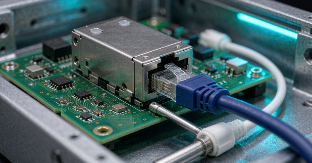
Ethernet LAN transformer selection starts with the exact PHY and its recommended magnetic circuit. Matching the speed label, a 1:1 turns ratio or the package outline alone does not establish compatibility. The useful comparison includes the transformer and choke topology, centre-tap connections, electrical limits with their test conditions, and the PCB implementation.
This guide applies to an Ethernet port using a standard RJ45 connector and separate signal magnetics. It helps OEM engineers and buyers prepare a defensible component shortlist and supplier enquiry. If the architecture is still undecided, GLGNET's integrated magnetic RJ45 versus standard RJ45 comparison addresses that earlier choice.
Start Ethernet LAN Transformer Selection with the PHY
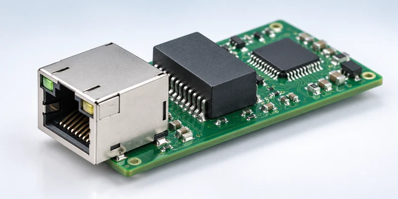
Record the PHY's full ordering code and obtain its datasheet, hardware checklist and applicable reference circuit. Include the intended Ethernet rates, number of ports, operating environment and whether the port supplies or receives PoE. A distributor description such as “gigabit Ethernet transformer” leaves too much unspecified for approval.
Selecting a LAN transformer for Ethernet PHY designs means matching the actual analogue interface. Identify the required number of magnetic channels, transformer ratio and tolerance, centre-tap access, common-mode choke arrangement and terminations. Check whether the PHY manufacturer recommends particular components or identifies a qualification process. Preserve the relevant document revisions with the comparison.
Microchip's VPPD-01740 Magnetics Guide illustrates this approach for the Microsemi Ethernet PHY families it discusses. Its suggested characteristics include centre-tap separation and an appropriate choke arrangement, alongside turns ratio and return loss. Those recommendations have a defined PHY context; they are not a universal specification for every Ethernet device or speed.
Treat recommended and qualified parts carefully. Microchip's AN8.13 suggested-magnetics page describes product-family tables with separate qualified and suggested categories. Retain that distinction when reviewing a list, including the specific PHY, configuration and document version. A supplier's cross-reference proposal needs an engineering comparison if its qualification scope is different.
Before comparing prices, ask the supplier to identify deviations from the reference circuit. A missing independent centre tap or different choke placement can affect whether the proposed component supports the design. Resolving that question after PCB layout may require more than substituting a footprint-compatible part.
Ethernet Magnetics Explained: Read the Full Test Conditions
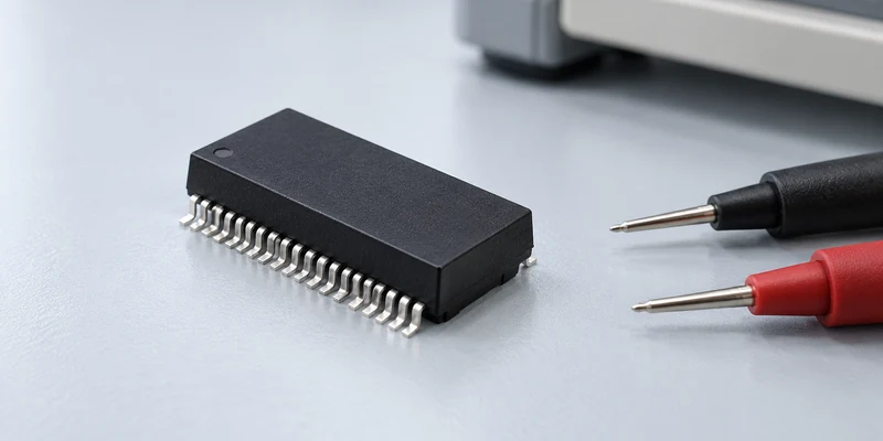
For OEM selection, Ethernet magnetics explained usefully means connecting each specification to its measurement conditions and circuit function. Two datasheet numbers are comparable only when they describe the same quantity under relevant conditions. Retain frequency ranges, excitation, bias, temperature and the specified terminals in the comparison.
| Parameter | Information to compare | Why it affects approval |
|---|---|---|
| Turns ratio | Ratio, tolerance and winding identification | Must match the PHY interface and amplitude requirements |
| Open-circuit inductance, or OCL | Minimum value, test frequency, signal amplitude, DC bias and temperature | A bare inductance value omits conditions that affect its meaning |
| Insertion and return loss | Limits across the required frequency bands and measurement reference | A single value does not describe broadband signal performance |
| Common-mode performance and crosstalk | Defined measurement, frequency bands and relevant channels | Different test definitions or channel arrangements can mislead |
| Isolation withstand | AC or DC method, voltage, duration and tested boundaries | A component test must match the applicable isolation requirement |
| DCR and current capability | Named winding or terminal, current basis and temperature conditions | Needed for the intended power path and thermal assessment |
| Centre taps and choke topology | Full schematic and independently accessible connections | Determines whether the intended interface can be implemented |
Microchip's AN2054 Gigabit Ethernet Design Guide, for example, associates its transmitter OCL recommendation with an 8mA DC-bias condition. Use that as an example of why conditions belong with the value, rather than imposing its recommendation on an unrelated PHY. Ask for clarification when the proposed transformer datasheet omits a condition required by the PHY documentation.
OCL test bias is also separate from the continuous current capability required by a PoE power path. A small-signal inductance test does not, by itself, establish permissible power current, winding temperature or performance with the relevant current imbalance. Keep the electrical magnetic limits and power-current evidence as separate entries.
Read the sign convention for loss specifications. Return loss may be expressed as positive attenuation or through a negative S-parameter representation; insertion loss can also be presented with different sign conventions. Compare the physical limit, frequency range and reference conditions before declaring that a numerically larger or smaller entry is better. Escalate unclear notation to the component manufacturer.
For sample comparisons, retain whether the data are guaranteed limits, typical curves or measurements from identified specimens. A typical room-temperature plot answers a different question from a guaranteed specification across the required environment. Request the evidence needed for the OEM's acceptance plan instead of treating all three as interchangeable.
Check Discrete Ethernet Magnetics Centre Taps and PoE Paths
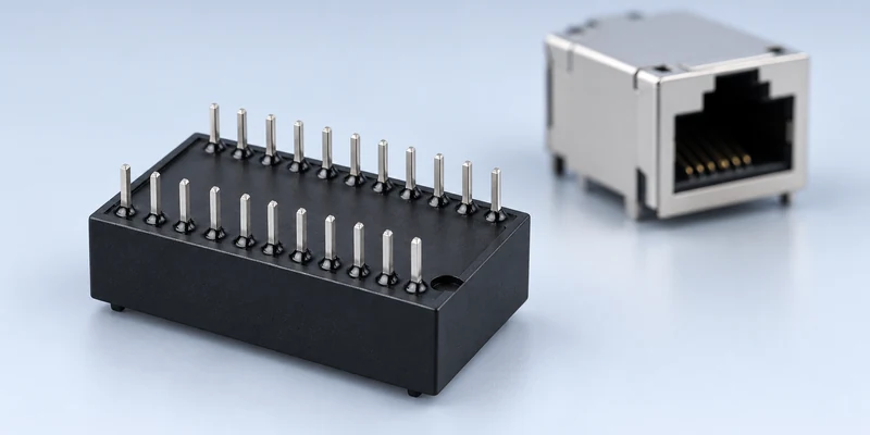
Compare discrete Ethernet magnetics schematics pin by pin. Mark the PHY-side and cable-side windings, centre taps and choke connections before reviewing the PCB footprint. Identical package dimensions can conceal different internal connections, while a shared internal node may prevent the external circuit the PHY requires.
Texas Instruments' DP83867 Troubleshooting Guide, SNLA246, specifies separate PHY-side centre taps connected to ground through decoupling capacitors for that device. A TI engineering support answer about the DP83867E also addresses an actual user's confusion between direct grounding and the required decoupling connection. The lesson for purchasing is specific: preserve the PHY's connection requirement when accepting a proposed substitute.
Where independent taps are required, adding a capacitor to a shared internal node does not make those taps independent. Check whether the package actually brings out the needed connections. Ask for a different internal topology if the proposed module cannot implement the reference circuit. This is a schematic compatibility decision; additional PCB pads or an apparently matching number of package pins cannot establish that the required internal connections exist.
Apply the same discipline to common-mode chokes. Microchip's VPPD-01740 discusses a line-side CMC recommendation within its stated device context. TI's industrial Ethernet EMC application note, SNLA466, discusses an additional PHY-side CMC for certain immunity improvements. These documents address different design contexts. They do not establish one choke location that every PHY and board must use.
For PoE, trace the actual DC route from the cable conductors through the appropriate windings and cable-side centre taps to the PSE or PD circuitry. Specify the intended power implementation, pairsets, terminal current conditions and relevant thermal requirements. Review winding resistance and applicable imbalance or saturation information with the supplier. A non-PoE part should not be promoted to a PoE candidate merely because its turns ratio and footprint match.
Keep the terminology precise when requesting samples. The Ethernet LAN transformer carries the data interface and its required isolation. A PoE converter may separately contain a transformer for DC/DC power conversion. A search or quotation for “PoE transformer” can therefore return a different component category. Identify the function and circuit location in the RFQ so the supplier proposes the signal magnetics actually required.
Discrete Ethernet Magnetics Package and PCB Checks
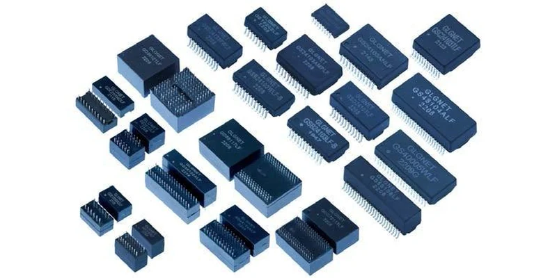
Once the circuit is compatible, compare mounting style, channel count, pin numbering, package height, footprint and the recommended PCB land pattern. Confirm the top or bottom viewing convention and pin-one orientation. Translate the complete schematic into the footprint review; a mechanical drawing alone cannot establish which terminals belong to the PHY and cable sides.
GLGNET's company profile, page 21, shows discrete LAN transformer packages and describes DIP and SMT options. Its catalogue PDF page 33, printed pages 57–58, includes a discrete-transformer table with package, pin-count, speed and PoE fields. These materials support a discussion of the product family. Obtain the current model-specific datasheet and drawing before treating a catalogue entry as an approved, currently available component.
Allow for the complete magnetic implementation. Bourns' network-transformer technical article describes both traditional modules and a chip-transformer approach using a separate common-mode component. This makes an important BOM distinction: a package described as a LAN transformer may not contain the same functions as another proposed magnetic module. Identify any additional chokes or terminations needed before comparing component count or PCB area.
Review the isolation boundary, differential routing, grounding and placement using the selected PHY's layout guidance and the equipment requirements. Keep cable-side and PHY-side connections identifiable in the design review. A discrete transformer that meets its component limits can still be installed in a layout that couples noise onto the interface or fails the required system test.
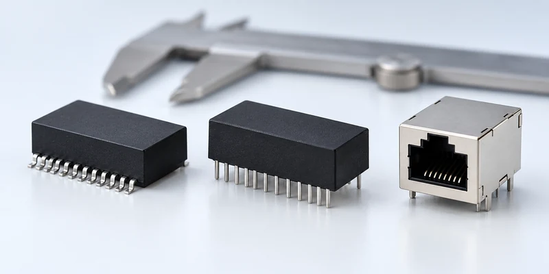
The standard jack remains a separate selection item. Confirm its contact arrangement, shield connection, mounting and any LED terminals against the complete front end. GLGNET's RJ45 jack connector range can support that discussion. Do not transfer an integrated MagJack's magnetic specification to a standard jack or use its combined footprint as the discrete transformer's land pattern.
Build an Ethernet LAN Transformer Selection and RFQ Matrix
Keep one comparison row for each proposed part and attach the evidence behind its approval status. The following inputs help a supplier narrow the options while exposing questions that need engineering review.
| RFQ input | Information to send or request |
|---|---|
| PHY and reference design | Full part number, document revisions and magnetic-interface circuit |
| Interface requirements | Target rates, ports, channel count and required circuit topology |
| Electrical matrix | Applicable ratio, OCL conditions, loss bands, common-mode and isolation requirements |
| PoE architecture | Non-PoE or PSE/PD role, powered pairsets and relevant current/thermal conditions |
| Mechanical implementation | Mounting, pin mapping, land pattern, height and board constraints |
| Environment and validation | Operating conditions, required system assessments and sample acceptance plan |
| Sourcing information | Reference transformer, proposed alternative, quantities and production milestones |
Use clear statuses such as confirmed, pending clarification and requires board change. If a candidate matches the package but combines centre taps that the PHY needs separately, record the actual mismatch. If it lacks a specified test condition, request that information rather than filling the blank with a similar model's value. This makes the shortlist reviewable by engineering and purchasing together.
Keep component evaluation and equipment qualification distinct. Verify the agreed magnetic specifications and then evaluate the assembled interface under the OEM's signal, interoperability and environmental requirements. Record the selected part and board revision with the results so a later supplier change can be assessed against the approved configuration.
Retain the source of each acceptance decision. A PHY vendor's suggested-parts list, a magnetic supplier's specification and an OEM system-test record provide different evidence. Attach the applicable one to each requirement rather than using a general “compatible” statement for the whole matrix. For a second source, identify which existing evidence still applies and what needs renewed assessment. This lets purchasing pursue supply options while keeping the engineering basis of the approved component visible.
For an external-magnetics enquiry, send GLGNET the PHY, reference circuit and transformer requirements, together with the target speed, PoE arrangement, reference component and PCB footprint. Its networking connectivity solutions provide context for coordinating the standard jack and magnetic component. Request the specific proposed drawing and datasheet for review before committing the design or BOM.
Ethernet LAN Transformer Selection FAQs
Can any 1:1 transformer work with an Ethernet PHY?
No. Turns ratio is one requirement. The PHY also needs the appropriate topology, centre-tap connections, electrical performance, isolation and channel arrangement. Confirm the exact component against the PHY documentation and evaluate it in the intended interface.
Why should OCL be read with its DC-bias test condition?
Inductance depends on the magnetic operating conditions. A value reported without the relevant bias, frequency, amplitude and temperature does not establish performance under another condition. Compare the stated test with the PHY's requirement and keep PoE continuous-current capability separate.
Can a standard RJ45 design with separate magnetics support PoE?
Yes, when the jack, signal magnetics, centre-tap circuit and complete PSE or PD implementation are suitable for the intended PoE operation. A standard jack alone does not establish that capability. Confirm the complete current path, component ratings and system requirements.
For related connector guidance, review the magnetic RJ45 mounting and soldering process guide, the PoE MagJack power rating comparison, the RJ45 gold plating thickness buying guide, the ganged vs. stacked magnetic RJ45 layout guide, and the industrial Ethernet connector selection guide. Browse GLGNET’s magnetic RJ45 connector portfolio for more.
SEND YOUR PHY, REFERENCE CIRCUIT AND TRANSFORMER REQUIREMENTS