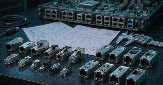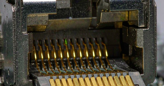
Choosing between a 2.5G, 5G and 10GBASE-T magnetic RJ45 connector is not simply a matter of selecting the highest data rate. The MagJack has to match the Ethernet PHY, magnetic topology, cable channel, PoE circuit, PCB footprint and operating environment as one system.
A 10G-rated part may provide useful bandwidth headroom, but it does not make a 2.5G device run faster and it is not automatically compatible with every Multi-Gig PHY. At the other extreme, selecting a lower-speed connector for a platform that will later move to 10G can force a PCB and enclosure redesign. The practical goal is to choose the lowest-risk part that meets the present specification and the realistic product roadmap.
2.5G vs 5G vs 10GBASE-T RJ45: Which Speed Fits the Application?
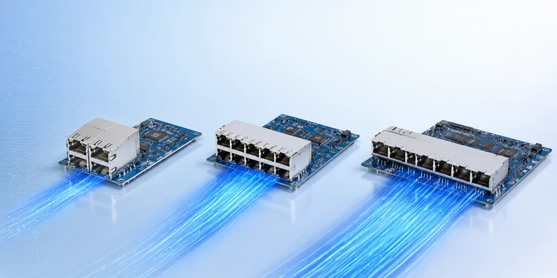
The three interfaces use the familiar copper Ethernet connection but serve different bandwidth and infrastructure needs. IEEE 802.3bz introduced 2.5GBASE-T and 5GBASE-T as intermediate rates between 1G and 10G. They allow equipment manufacturers to deliver more bandwidth over much of the installed Cat5e and Cat6 cabling base, which is especially useful for wireless access points, gateways, workstations and access switches.
| Decision factor | 2.5GBASE-T | 5GBASE-T | 10GBASE-T |
|---|---|---|---|
| Maximum rate | 2.5 Gbps | 5 Gbps | 10 Gbps |
| Typical reason to use | Economical step above 1G | More AP or storage headroom | Full 10G copper access |
| Common equipment | Wi-Fi APs, gateways, edge devices | High-end APs, NAS, workstations | Servers, switches, storage |
| Cable planning | Cat5e or better | Cat5e/Cat6; verify channel | Cat6A preferred for 100 m |
| Design burden | Moderate | Higher | Highest signal and thermal attention |
- A 2.5GBASE-T RJ45 is often the most efficient choice when the link only needs to remove the 1G bottleneck. A 5GBASE-T design makes sense when sustained traffic can exceed 2.5Gbps but a full 10G architecture is not justified. A 10G RJ45 belongs in systems that genuinely need 10Gbps copper access or must preserve compatibility with an installed RJ45 environment at that speed.
- Do not use the connector rating as a substitute for system planning. Auto-negotiation and supported link rates are functions of the PHYs at both ends. A 10G-capable MagJack can pass the required signal bandwidth, but the device will only negotiate 2.5G or 5G if the PHY, firmware and link partner support those modes.
Multi-Gig MagJack Selection by Cable, PHY and PCB Channel
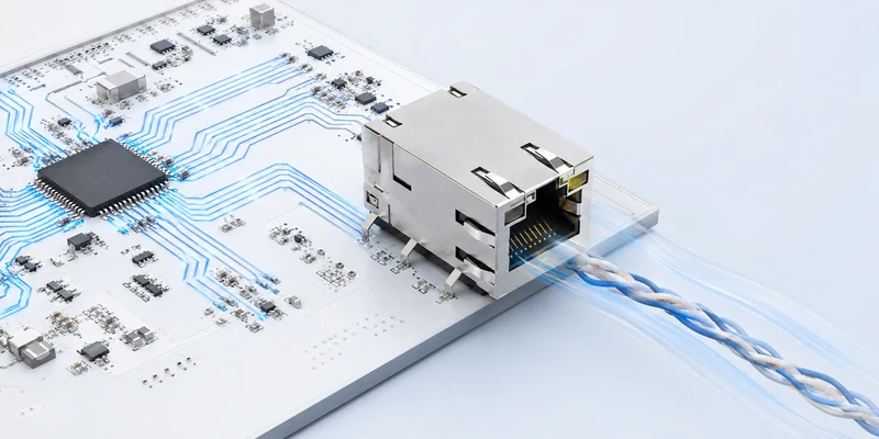
Cable capability affects the complete link, not just the patch cord. 2.5GBASE-T is designed to operate over commonly deployed Cat5e cabling at standard Ethernet channel lengths. 5GBASE-T can also use existing copper, but its margin becomes more sensitive to cable quality, bundled runs, patch panels, termination workmanship and alien crosstalk. For 10GBASE-T, Cat6A is the normal choice when a 100-meter channel is required; Cat6 may support shorter 10G links under suitable conditions.
Inside the equipment, the PHY-side differential pairs should maintain controlled impedance, consistent spacing and a continuous reference environment. Avoid unnecessary vias, stubs and abrupt geometry changes. Keep the pairs away from switching regulators, clocks and other strong noise sources. A well-rated RJ45 with integrated magnetics cannot recover margin already lost through a poor board channel or shield termination.
The cable-side region also deserves attention. The shield needs a deliberate chassis or grounding strategy, and the isolation boundary specified by the equipment design must be maintained. Qualification should use the intended PCB, enclosure and cable configuration rather than treating the connector as an isolated component.
RJ45 with Integrated Magnetics: Current-Mode or Voltage-Mode PHY?
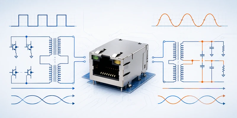
One of the most important checks is whether the MagJack magnetic circuit matches the PHY implementation. Multi-Gig PHYs may use different line-driver architectures and reference circuits. The connector selection therefore has to follow the PHY vendor’s reference design, not a generic “2.5G/5G/10G” label.
In a current-mode implementation, center taps and supply connections may be used differently from a voltage-mode implementation. The transformer turns ratio, center-tap routing, common-mode choke arrangement and termination network must agree with the PHY documentation. If the topology is wrong, the system may show weak margin, failed compliance tests, unstable links or no link at all.
Before approving an integrated magnetics RJ45, compare its internal schematic with the PHY reference schematic. Confirm the transformer ratio, open-circuit inductance, insertion loss, return loss, common-mode rejection, isolation and any required bias or termination components. Where available, use a MagJack that has already been evaluated with the selected PHY family, but still review the exact part and board implementation.
10GBASE-T Magnetic RJ45 Signal Integrity and EMI Requirements
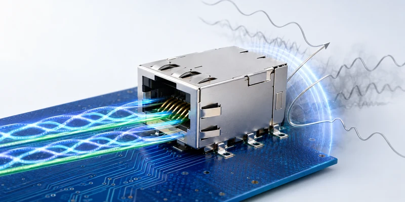
Signal integrity limits become tighter as the data rate rises. Return loss indicates how much energy is reflected by impedance discontinuities. Insertion loss describes attenuation through the signal path. Crosstalk and balance measurements show how effectively the four-pair channel controls unwanted coupling and common-mode conversion. These parameters matter at 2.5G and 5G and become especially important in a 10GBASE-T magnetic RJ45 design.
Do not compare products only by isolation voltage, contact resistance or external dimensions. The relevant datasheet should show electrical performance across the frequency range required by the target Ethernet standard. If a vendor only states “10G” without providing a magnetic schematic and suitable high-frequency data, the part should not be treated as validated for the design.
EMI performance depends on more than the metal shell. Common-mode chokes, transformer balance, shield fingers, chassis contact, enclosure openings and PCB return paths all influence emissions and immunity. For dense switches or industrial equipment, review adjacent-port coupling and the mechanical continuity between the connector shield and front panel. Final confidence comes from board-level signal-integrity and EMC testing, not from the connector specification alone.
PoE and PoE++ Magnetic RJ45: Power Topology and Thermal Checks
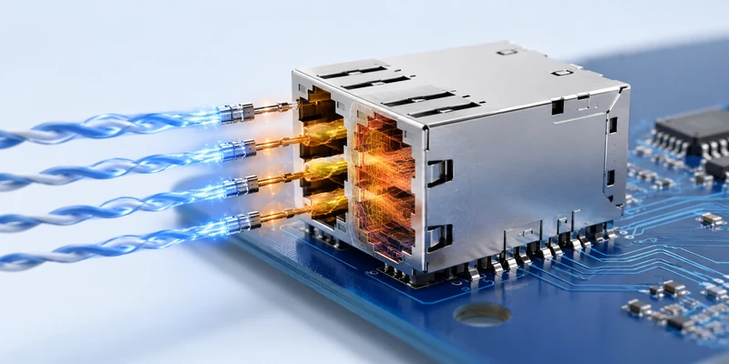
Ethernet speed and PoE capability must be specified separately. A connector rated for 10G data is not automatically suitable for PoE++, and a PoE-capable product may not support the current, topology or temperature required by the project.
First confirm whether the system uses IEEE 802.3af, 802.3at or 802.3bt and whether power is delivered through two or four pairs. The magnetic center taps, contact system and PCB power path must carry the required current. Winding resistance and contact resistance generate heat, so the evaluation should consider current per pair, maximum ambient temperature, port density, airflow and duty cycle together.
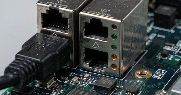
High-power projects should ask for current rating, temperature-rise data, winding resistance, contact resistance and the supported PoE circuit. A maximum wattage printed on a product page is not enough to confirm safe operation in a sealed device or a multi-port switch. GLGNET’s company information states support for PoE levels from 15W, 30W, 60W and 90W through custom configurations up to 150W; the exact PoE++ magnetic RJ45 still needs to be matched to the project circuit and thermal conditions.
Magnetic RJ45 Connector Structure: 1×1, 1×N, Vertical or Right-Angle
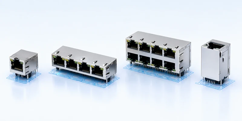
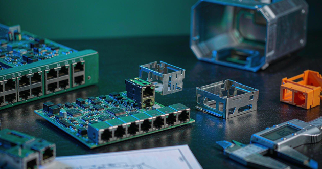
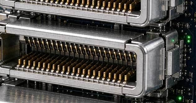
After the electrical design is defined, the connector must fit the PCB, enclosure and assembly process. A 1×1 right-angle part is common for a single side-entry port. A ganged 1×N configuration can reduce assembly complexity in a multi-port switch, while a stacked 2×N connector increases front-panel density. Vertical and slant-angle versions are useful when the port enters from the top or must follow a specialized enclosure layout.
Mechanical similarity does not guarantee interchangeability. Two magnetic RJ45 connector products can have the same port count and nearly identical external dimensions but use different signal pins, LED pins, shield tabs, locating posts or board locks. Compare the recommended PCB layout, datum positions, connector height, latch direction and panel opening before calling a part a drop-in replacement.
Mounting also affects manufacturing. Through-hole DIP remains common for mechanical retention, while SMT, press-fit and pin-in-paste options may suit different board and assembly strategies. LED color, polarity and circuit should be confirmed at the same time because a late LED change can alter both the pinout and customer-facing indication logic.
How to Choose a 2.5G, 5G or 10G RJ45 MagJack by Use Case
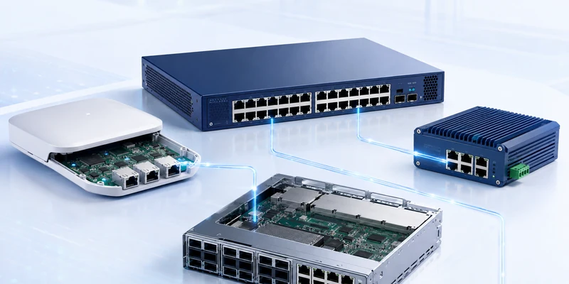
For a Wi-Fi 6E or Wi-Fi 7 access point, begin with the real uplink requirement and PoE load. A 2.5G port may be sufficient for a cost-sensitive access model, while 5G can provide additional headroom for higher radio capacity. If the AP requires high-power PoE, thermal and center-tap requirements may determine the connector before the speed decision does.
For routers, gateways and industrial edge equipment, 2.5G or 5G often offers a useful balance between performance, cable reuse and platform cost. In electrically noisy machinery, signal balance, shield grounding and operating temperature may be more important than selecting the maximum nominal rate.
For servers, storage and high-performance switches, a 10G RJ45 MagJack is appropriate when copper compatibility and 10Gbps access are required. High-port-density equipment should evaluate power and temperature across all active ports, not one connector in isolation. If the design instead prioritizes lower power, very high density or longer reach, the separate question of SFP+, DAC or fiber should be reviewed on the existing GLGNET interface comparison page rather than repeated here.
What to Send a Magnetic RJ45 Connector Supplier for an RFQ
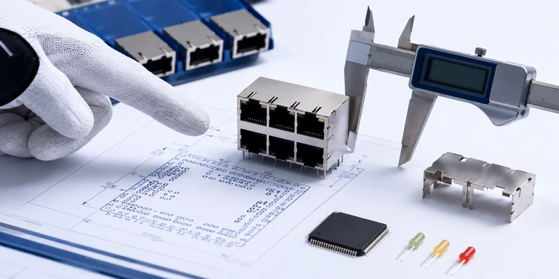
A supplier can recommend a compatible part much faster when the inquiry contains system-level information. A request for “a 10G MagJack” leaves too many variables unresolved and often leads to repeated drawings, sample rounds or incorrect substitutions.
- Target Ethernet rate: 2.5GBASE-T, 5GBASE-T, 10GBASE-T and any required fallback rates.
- PHY information: manufacturer, full part number and the relevant reference schematic.
- PoE requirement: IEEE class, two-pair or four-pair powering, required wattage and current per pair.
- Port configuration: 1×1, ganged 1×N, stacked 2×N and required latch orientation.
- Mounting process: through-hole, SMT, press-fit, pin-in-paste or another assembly requirement.
- LED and shield details: LED colors and circuit, EMI fingers, gasket and chassis connection.
- Mechanical limits: PCB footprint, maximum connector height, panel opening and enclosure constraints.
- Environment and replacement data: operating temperature, application, current part number, drawing or sample.
For an existing design, the current part number and PCB drawing are especially valuable. They allow the supplier to check the footprint and internal schematic together instead of comparing only the outer dimensions.
Final 2.5G vs 5G vs 10GBASE-T RJ45 Selection Checklist
Choose 2.5G when the system needs a practical upgrade from 1G and will continue to use common Cat5e infrastructure. Choose 5G when the expected traffic can exceed 2.5Gbps but the product does not require a full 10G copper channel. Choose 10G when the device genuinely needs 10Gbps access and the PHY, PCB, cable and thermal design are prepared for the tighter requirements.
Whichever rate is selected, verify the PHY topology, internal magnetic schematic, signal-integrity data, PoE current path, footprint, LED circuit, shield connection and operating temperature before releasing the board. That review matters more than choosing the part with the highest headline specification.
GLGNET provides RJ45 with magnetics from 10/100M through 10GBASE-T, with different port structures, mounting methods, LED and shielding options, plus PoE and custom high-power designs. Sending the PHY number, PoE requirement, PCB constraints and reference part allows the engineering team to narrow the selection before sample testing.
Explore the GLGNET Magnetic RJ45 connector range, review the broader
GLGNET networking connectivity solutions, or read
RJ45 MagJack Design Mistakes before finalizing the board design.