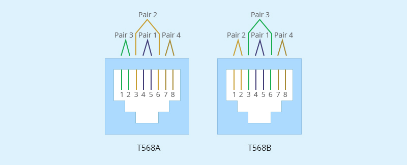
A correct RJ45 pinout is essential for stable Ethernet cable wiring. Whether you are working with Cat5e, Cat6, or Cat6A cables, the right T568A or T568B wire order helps prevent connection failures, slow network speed, and PoE device issues. This guide explains how to wire an RJ45 connector step by step, avoid common mistakes, and choose reliable RJ45 connectivity solutions for network applications.
What Is an RJ45 Pinout?
An RJ45 pinout is the position order of the eight conductors inside an RJ45 Ethernet connector. Each conductor must enter the correct contact position so that the cable can transmit data properly.
Most Ethernet cables, including Cat5e, Cat6, and Cat6A, contain four twisted pairs. These pairs are arranged into eight pin positions inside the RJ45 connector. The two common wiring layouts are T568A and T568B.
The important point is this: RJ45 pinout is not only a color order. It also depends on keeping the correct wire pairs together, inserting the wires fully, choosing the right connector, and testing the finished cable. A cable can fail even when the color sequence looks correct if the conductors are not seated or crimped properly.
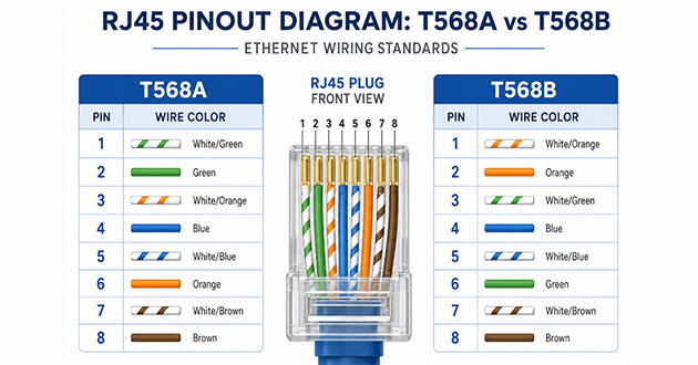
RJ45 Pinout Diagram: T568A and T568B
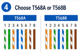
T568A and T568B use the same wire colors, but the orange and green pairs change positions. The blue pair and brown pair stay in the same positions in both standards.
T568A RJ45 Pinout
Pin | Wire Color |
1 | White/Green |
2 | Green |
3 | White/Orange |
4 | Blue |
5 | White/Blue |
6 | Orange |
7 | White/Brown |
8 | Brown |
T568B RJ45 Pinout
Pin | Wire Color |
1 | White/Orange |
2 | Orange |
3 | White/Green |
4 | Blue |
5 | White/Blue |
6 | Green |
7 | White/Brown |
8 | Brown |
The easiest way to check the difference is to look at the first two pins:
T568A begins with White/Green, Green
T568B begins with White/Orange, Orange
For a standard Ethernet patch cable, use the same wiring standard on both ends.
T568A vs T568B: Which RJ45 Pinout Should You Use?
The better choice is not always the one you personally prefer. The better choice is the one that matches the network you are working on.
T568A and T568B can both support normal Ethernet communication when terminated correctly. They do not make the cable faster or slower by themselves. Network performance depends more on cable category, cable length, device capability, pair integrity, and termination quality.
Use this decision table instead of guessing.
Situation | Better Choice | Reason |
Existing cabling already uses T568A | T568A | Keeps the new cable consistent with wall jacks and patch panels |
Existing cabling already uses T568B | T568B | Avoids mixed wiring in the same system |
New commercial or office patch cable | Usually T568B | Common in many business Ethernet environments |
Residential structured cabling | Follow project requirement | Some residential systems may use T568A |
You are not sure what the site uses | Inspect first | Do not crimp before checking the existing standard |
You intentionally need a crossover cable | One end A, one end B | Used only for specific or older device-to-device connections |
The most common mistake is not choosing T568A or T568B. The most common mistake is using one standard on one end and another standard on the other end without realizing it.
For normal Ethernet wiring:
T568A to T568A = straight-through cable
T568B to T568B = straight-through cable
T568A to T568B = crossover cable
If you are replacing a cable in an existing cabinet, do not assume the old cable uses T568B. Check the other end, the patch panel, or the wall jack before making a new termination.
Tools and Materials You Need to Set Up an RJ45 Pinout
The tools are simple, but each one prevents a different type of failure. Instead of seeing the tool list as a formality, treat it as a quality-control checklist.
Tool or Material | What It Helps Prevent |
Ethernet cable | Prevents mismatch between application speed and cable capability |
Correct RJ45 connector | Prevents poor fit, incomplete insertion, and weak contact |
Cable cutter | Prevents crushed or uneven cable ends |
Wire stripper | Prevents conductor damage during jacket removal |
Crimping tool | Prevents loose contact and weak mechanical grip |
Cable tester | Prevents hidden wiring faults from being installed |
Punch-down tool | Needed for keystone jacks or patch panels, not standard plug crimping |
For simple RJ45 plug termination, the essential items are Ethernet cable, RJ45 plugs, a crimping tool, a wire stripper, a cutter, and a cable tester.
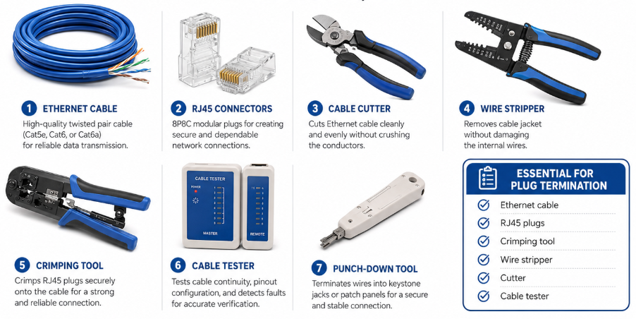
For keystone jacks, patch panels, or wall outlets, the termination method is different. Those usually require punch-down termination rather than crimping a plug onto the cable end.
How to Wire an RJ45 Connector Step by Step
The goal of RJ45 wiring is not just to finish the crimp. The goal is to create a cable that still works after it is moved, installed, connected to equipment, and used under real network load.
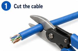
Step 1: Cut the Cable Cleanly
Cut the Ethernet cable to the required length. Leave enough extra length for routing and service access, especially inside cabinets or equipment racks.
A poor cut can flatten the cable end and make the wires harder to arrange. If the end is crushed, cut it again before stripping.
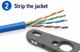
Step 2: Remove the Outer Jacket
Strip about 1 inch, or around 2.5 cm, of the cable jacket. The cut should remove the jacket without touching the insulation of the internal conductors.
After stripping, inspect the wires. If you see a nicked conductor or exposed copper, do not continue. Cut the damaged section away and restart.
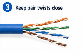
Step 3: Keep the Pair Structure as Much as Possible
Separate the four twisted pairs only as much as needed for ordering the wires. Do not untwist the cable deeply into the jacket.
This matters more for Cat6 and Cat6A cable. The more the pairs are opened, the more the cable may lose its noise-control advantage near the connector. A short, neat termination is usually better than a long, loose one.
Step 4: Confirm the Wiring Standard Before Ordering the Wires
Choose T568A or T568B before you arrange the conductors. If this cable connects to existing wiring, check the existing system first.
A good habit is to ask:
Is this a new cable or part of an existing installation?
Does the patch panel already use T568A or T568B?
Does the wall jack follow a marked standard?
Am I making a straight-through cable or a crossover cable?
This avoids the common mistake of finishing one end correctly but matching it to the wrong standard on the other end.
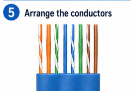
Step 5: Arrange the Conductors
Place the wires in the correct order for your selected standard.
For T568A:
White/Green
Green
White/Orange
Blue
White/Blue
Orange
White/Brown
Brown
For T568B:
White/Orange
Orange
White/Green
Blue
White/Blue
Green
White/Brown
Brown
The most error-prone positions are pins 1, 2, 3, and 6 because the orange and green pairs change places between T568A and T568B.
Step 6: Trim the Wire Ends Evenly
Once the conductors are in order, hold them flat and trim the ends evenly. Uneven wires are one of the most common reasons a connector looks fine but fails testing.
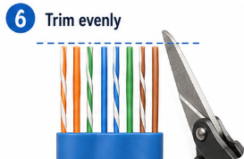
Each wire should be long enough to reach the front of the plug. If one wire is short, the metal blade may not contact the conductor after crimping.
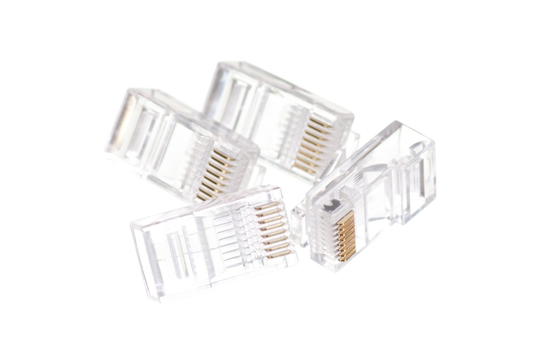
Step 7: Insert the Wires into the RJ45 Plug
Slide the conductors into the RJ45 connector slowly. Each wire should enter a separate channel and remain in the correct order.
Before crimping, look through the transparent plug body. Confirm that:
All eight wire tips reach the front of the connector
No wire has crossed into the wrong channel
The cable jacket enters the rear of the plug
The conductors are still in the selected T568A or T568B order
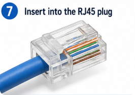
The jacket position is important. If the jacket does not enter the plug far enough, the cable may pass a basic test but fail later when pulled, bent, or moved.
Step 8: Crimp Once, Then Inspect
Insert the connector into the crimping tool and press firmly. The contacts should pierce into the conductors, and the rear strain relief should grip the cable jacket.
After crimping, do not immediately assume it is correct. Inspect it again:
Are all contacts pressed down evenly?
Is the plug firmly attached?
Are all wires still visible at the front?
Does the jacket stay inside the strain relief area?
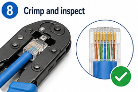
If anything looks wrong, cut off the connector and start again. A crimped RJ45 plug should not be reused.
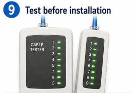
Step 9: Test Before Installation
Test the cable before placing it in a wall, cabinet, ceiling, or equipment rack. Re-crimping is easy on a workbench but difficult after the cable is installed.
For a straight-through cable, the tester should show the same pin order from one end to the other. If the tester shows an open, short, crossed wire, or wrong sequence, cut off the plug and terminate the cable again.
RJ45 Pinout Table for Quick Reference
Pin | T568A Color | T568B Color |
1 | White/Green | White/Orange |
2 | Green | Orange |
3 | White/Orange | White/Green |
4 | Blue | Blue |
5 | White/Blue | White/Blue |
6 | Orange | Green |
7 | White/Brown | White/Brown |
8 | Brown | Brown |
Quick check:
End A | End B | Cable Type |
T568A | T568A | Straight-through |
T568B | T568B | Straight-through |
T568A | T568B | Crossover |
T568B | T568A | Crossover |
Straight-Through vs Crossover RJ45 Pinout
A straight-through cable uses the same wiring standard on both ends. This is the normal cable type for most Ethernet connections, including computers, switches, routers, access points, IP cameras, and patch panels.
A crossover cable uses T568A on one end and T568B on the other. It was traditionally used for direct connections between similar devices, such as computer-to-computer or switch-to-switch links.
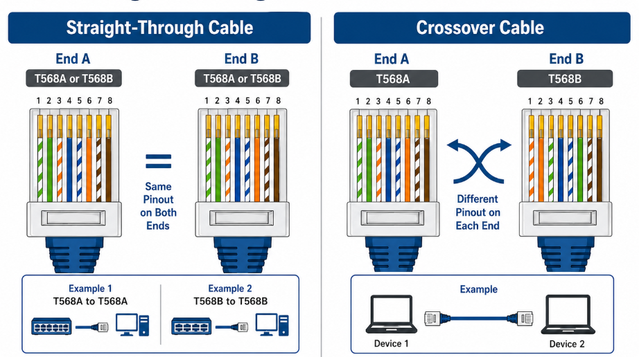
Modern devices often support automatic pair correction, so crossover cables are less common than before. Still, understanding the difference helps when troubleshooting older devices, test setups, or unusual network connections.
For most home, office, and equipment wiring, choose a straight-through cable unless there is a clear reason to use crossover wiring.
RJ45 Pinout for Cat5e, Cat6 and Cat6A Ethernet Cables
The T568A and T568B color order can be used for Cat5e, Cat6, and Cat6A Ethernet cables. The pinout does not change just because the cable category changes.
The difference is in the termination difficulty.
Cable Type | Pinout Standard | Main Termination Concern |
Cat5e | T568A or T568B | Correct order and clean crimping |
Cat6 | T568A or T568B | Pair control and connector fit |
Cat6A | T568A or T568B | Cable thickness, shielding, and contact reliability |
Cat5e
Cat5e cable is usually easier to terminate. It is more flexible and often fits standard RJ45 plugs more easily. For Cat5e, most problems come from wrong color order, weak crimping, or wires not reaching the front of the plug.
Cat6
Cat6 cable requires more careful handling. The pairs may be tighter, and some cables include a separator inside the jacket. When terminating Cat6, keep the pairs neat and avoid opening the twist too far from the connector.
Connector matching also becomes more important. A connector designed for smaller cable may not hold Cat6 conductors correctly.
Cat6A
Cat6A is more sensitive to poor termination. The cable may be thicker, less flexible, shielded, or built with larger conductors. If the RJ45 connector does not match the cable structure, the wire order may be correct but the connection may still be unreliable.
Many Cat6A failures are not caused by the wrong T568A or T568B table. They are caused by using the wrong connector or by incomplete termination.
Common Mistakes When Setting Up an RJ45 Pinout
RJ45 mistakes are easier to fix when you connect the symptom with the possible cause.
Mistake | Typical Symptom | Why It Happens | Better Fix |
Wrong color order | Tester sequence fails or no link | Wires do not match T568A/T568B | Re-terminate with correct order |
A/B mismatch | Unexpected crossover cable | One end uses A, the other uses B | Match both ends unless crossover is intended |
Wire not fully inserted | One pin fails or link drops | Contact blade misses the conductor | Trim evenly and insert fully |
Too much untwisting | Speed is unstable | Pair balance is weakened near the plug | Keep twists close to the connector |
Weak crimp | Cable fails when moved | Poor contact or weak strain relief | Use a suitable crimping tool |
Wrong plug for cable | Hard insertion or loose fit | Connector does not match cable size | Use the correct RJ45 connector |
Damaged conductor | Open wire on tester | Jacket stripping cut into the wire | Cut and restart |
No testing | Problem appears after installation | Fault was never verified | Test before use |
The most dangerous mistake is assuming that a cable is correct because it “looks right.” Ethernet cable problems are often hidden inside the connector. Always inspect and test.
How to Test an RJ45 Pinout After Crimping
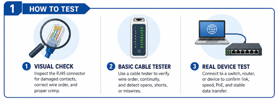
Visual Check
Start with the connector itself. Look for full conductor insertion, correct color order, even contact pressure, and proper jacket grip. If the jacket is outside the plug, the connection may not survive movement or pulling.
Basic Cable Tester
A basic tester checks pin continuity and sequence. For a straight-through cable, pins should run 1 to 1, 2 to 2, 3 to 3, and so on.
Common results:
Tester Result | Meaning |
One pin does not light | Open conductor |
Two pins light together | Short circuit |
Sequence is wrong | Miswire |
A/B pattern appears | Crossover wiring |
Tester passes but network is slow | Possible pair or performance issue |
Real Device Test
A basic tester is useful, but it does not always confirm full performance. After testing continuity, connect the cable to actual equipment and check:
Does the link stay stable?
Does the port negotiate the expected speed?
Does the cable work when moved slightly?
Does a PoE device power on and remain stable?
Does data transfer behave normally?
If the cable passes a simple tester but only connects at 100 Mbps instead of 1 Gbps, one pair may be poorly terminated, damaged, or incorrectly paired.
Troubleshooting RJ45 Connection Problems
Troubleshooting is easier when you start with the symptom instead of randomly re-crimping the cable.
Problem | Most Likely Area to Check |
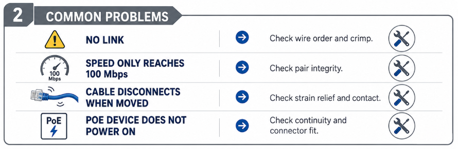
No link at all | Wire order, open conductor, bad crimp |
Tester shows wrong order | T568A/T568B sequence |
Link light on but no stable connection | Pair alignment or weak contact |
Speed only reaches 100 Mbps | One pair may not be working correctly |
Cable disconnects when moved | Strain relief or weak crimp |
PoE device does not power on | Contact quality, conductor continuity, cable suitability |
Cat6A cable is hard to terminate | Connector and cable compatibility |
No Link
Check the basic pinout first. If the wire order is correct, inspect whether each conductor reaches the end of the plug. A single open conductor can stop the cable from working.
Low Speed
If the cable connects but does not reach the expected speed, do not only look at the color order. Check for split pairs, excessive untwisting, damaged conductors, or a connector that does not match the cable.
Intermittent Connection
If the link drops when the cable is touched or moved, the problem is usually mechanical. The jacket may not be gripped, the crimp may be weak, or a conductor may be barely touching the contact.
PoE Failure
PoE adds another layer of reliability demand. A poor RJ45 termination may pass basic data connection but fail to deliver stable power. Check the connector fit, crimping pressure, cable category, and continuity before replacing the device.
RJ45 Connector Applications
RJ45 connectors are used across many Ethernet systems, but each application has a different priority.
Application | What to Prioritize |
Home network | Simple straight-through wiring and basic testing |
Office cabling | Consistent T568A/T568B standard across all points |
Data center | Labeling, cable management, and reliable testing |
IP camera and PoE system | Contact stability and power delivery |
Industrial Ethernet | Shielding, vibration resistance, and interference control |
Smart home and IoT | Stable wired connection in compact spaces |
Network equipment | Reliable device-side RJ45 interface |
For simple patch cables, correct pinout and testing may be enough. For PoE, industrial, or equipment-level applications, connector quality and long-term contact reliability become more important.
FAQ About RJ45 Pinout
1.What is the correct RJ45 pinout?
The correct RJ45 pinout depends on whether you use T568A or T568B. For a standard straight-through Ethernet cable, use the same standard on both ends.
2.Should I use T568A or T568B?
Use the standard already used in the existing network. If there is no existing requirement, T568B is commonly used in many commercial Ethernet installations.
3.Does T568A or T568B affect network speed?
No. The wiring standard itself does not decide the speed. Cable category, cable length, termination quality, and device capability have a greater impact.
4.Can I use T568A on one end and T568B on the other?
Yes, but that creates a crossover cable. For normal Ethernet patch cables, both ends should usually use the same standard.
5.Is the RJ45 pinout the same for Cat5e, Cat6 and Cat6A?
The T568A and T568B color order can be the same. However, Cat6 and Cat6A cables may require more careful termination and better connector matching.
6.Why does my cable tester pass but the network speed is still low?
A basic tester may confirm continuity but not full signal quality. Low speed may come from split pairs, excessive untwisting, poor contact, damaged cable, or a connector mismatch.
7.How much should I untwist the wire pairs?
Untwist only enough to arrange the wires into the connector. Keeping the twist close to the plug helps maintain better signal stability.
8.Can I reuse an RJ45 plug after a failed crimp?
No. Once an RJ45 plug has been crimped, it should be replaced. Cut it off and use a new connector.
9.Should shielded Ethernet cable use a shielded RJ45 connector?
Yes, if you want to maintain the shielding path. This is especially important in industrial, PoE, or high-interference environments.
10.Why does my PoE device fail after crimping a new RJ45 connector?
The issue may be weak contact, incomplete conductor insertion, wrong cable type, poor crimping, or connector mismatch. Check both the pinout and the mechanical quality of the termination.
About GLGNET RJ45 Connectivity Solutions
RJ45 pinout focuses on cable wiring, while stable network equipment also depends on reliable device-side RJ45 interfaces.
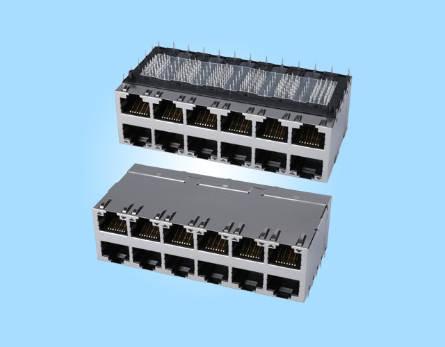
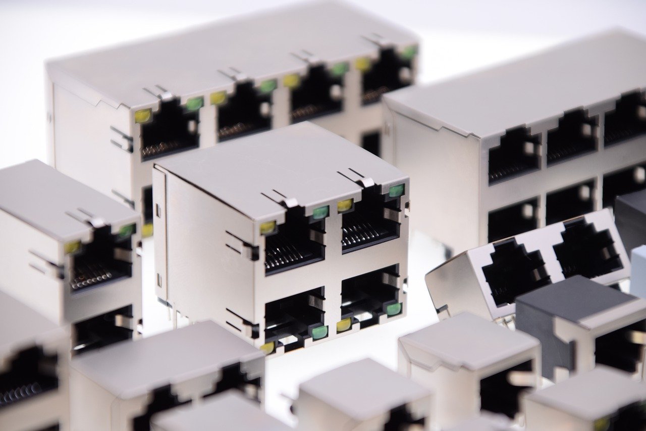
GLGNET provides RJ45 jacks, magnetic RJ45 connectors, shielded RJ45 connectors, and related Ethernet connectivity solutions for network equipment, industrial Ethernet devices, PoE systems, communication modules, and PCB-mounted applications.
For RJ45 connector selection or Ethernet interface design support, GLGNET can help match products based on shielding, magnetics, LED options, port direction, PCB layout, and application requirements.
Conclusion
By understanding T568A, T568B, straight-through wiring, crossover cables, and Cat5e/Cat6/Cat6A termination requirements, users can reduce wiring failures and improve network reliability. For device-side RJ45 interface needs, GLGNET provides reliable RJ45 connectivity solutions for network equipment and industrial applications.