This article walks through QSFP connector types by data rate and technology, the main cable and media options, and the key mechanical variations in cages and housings. Along the way, we show how GLGNET’s QSFP cage and connector portfolio ties these pieces together into practical, production-ready solutions from 40G to 800G.
QSFP Connector Types by Data Rate & Technology
|
QSFP Type |
Lanes |
Per-Lane Speed |
Total Rate |
Typical Use |
GLGNET Cage Options |
|
QSFP+ (40G) |
4 × electrical |
10 Gbps |
40 Gbps |
40GbE uplink / aggregation |
1×1, multi-port QSFP+ cages |
|
QSFP28 (100G) |
4 × electrical |
25 Gbps (NRZ) |
100 Gbps |
100G spine–leaf, 25G breakout |
1×1, 1×3, 1×4, 2×N, with HS / LP |
|
QSFP56 (200G) |
4 × electrical |
50 Gbps (PAM4) |
200 Gbps |
200G HPC / AI clusters |
QSFP56 high-speed cages |
|
QSFP-DD (400G) |
8 × electrical |
50 Gbps (PAM4) |
400 Gbps |
400G data center fabrics |
QSFP-DD cages with HS / EMI |
|
QSFP-DD800 |
8 × electrical |
100 Gbps (PAM4) |
800 Gbps |
800G backbone / AI fabrics |
QSFP-DD800 cages |
|
QSFP112 (400G) |
4 × electrical |
100 Gbps (PAM4) |
400 Gbps |
Compact 400G ports |
QSFP112 4-lane cages |
1.QSFP+ (40G) – 4×10G Lane Architecture
QSFP+ was one of the earliest QSFP connector platforms to be deployed at scale for 40GbE. It combines four 10G electrical lanes to deliver a 40 Gbps link and is still widely seen in Top-of-Rack uplinks, aggregation layers and networks that are gradually migrating toward 100G. For these scenarios, GLGNET supplies QSFP+ cages in both 1×1 and multi-port layouts, giving switch and server designers the freedom to tune front-panel density, cost and board layout without changing the basic form factor.
2.QSFP28 (100G) – Mainstream 100G Ethernet
QSFP28 keeps the same four-lane concept but increases each lane to 25 Gbps using NRZ signaling, delivering 100 Gbps in a compact, familiar footprint. It has become the workhorse of today’s 100G networks, supporting popular standards such as SR4, LR4 and CWDM4, and is widely used in spine–leaf fabrics and 25G server breakout designs. To support these deployments, GLGNET offers a broad QSFP28 cage portfolio including 1×1, 1×3, 1×4, 2×1, 2×2, 2×3 and 2×6 stacked options, with available heat sinks and light pipes that simplify thermal management and front-panel LED indication.
3.QSFP56 (200G) – PAM4-Based 200G
QSFP56 moves to PAM4 modulation and doubles the effective bandwidth of QSFP28 by running each of the four lanes at 50 Gbps. The result is a 200G interface that nicely bridges the gap between 100G and 400G, making it a good fit for high-performance computing, AI/ML clusters and other traffic-heavy environments that don’t yet require 400G everywhere. GLGNET includes QSFP56 cages in its high-speed product range (covering roughly 40–800G), helping engineers design 200G ports with solid signal integrity and well-controlled EMI performance.
4.QSFP-DD & QSFP-DD800 (400G to 800G)
QSFP-DD (Double Density) extends the traditional QSFP outline by adding a second row of contacts, increasing the lane count from four to eight. This enables 400G links with 8×50G PAM4 and, in the QSFP-DD800 evolution, 800G links with 8×100G PAM4. These form factors target next-generation spine–leaf fabrics, hyperscale cloud networks and AI data centers where port count and throughput both matter. GLGNET’s QSFP-DD and QSFP-DD800 cages are engineered for 8-lane operation up to 800 Gbps, with mechanical strength, EMI shielding and thermal features tuned for high-power 400G/800G optical modules.
5.QSFP112 – 4×100G Lanes for 400G
QSFP112 reaches 400 Gbps using just four very high-speed lanes, each operating at 112G PAM4. Compared with the 8×50G approach of QSFP-DD, QSFP112 offers another way to build 400G ports: fewer lanes, higher per-lane speed and a more compact electrical interface. This gives system designers a genuine architectural choice—QSFP-DD (8×50G) or QSFP112 (4×100G)—depending on their goals for faceplate density, power consumption and signal integrity. GLGNET’s QSFP112-focused cages are optimized for these 4×100G designs and complement its QSFP-DD offerings, allowing customers to choose the 400G strategy that best fits their platform roadmap.
6.Quick Comparison Table (Planned)
To make these form factors easier to compare, this section can be followed by a concise table showing each QSFP connector type alongside its lane count, per-lane speed, total bandwidth, typical deployment scenario and the corresponding GLGNET cage options. This gives readers a quick way to match their required data rate and topology with the most suitable QSFP generation and hardware platform.
QSFP Cage by Cable & Media Type (DAC, AOC, MMF, SMF)
Beyond the QSFP connector itself, the choice of cable and optical media largely determines how far a link can run, what it costs, and how easy it is to install and maintain. Below is an overview of the main media types commonly paired with QSFP ports in real deployments.
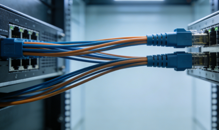
1. Direct Attach Copper (DAC)
Direct Attach Copper (DAC) is a passive copper assembly with QSFP connectors fixed on both ends. It’s typically used for very short runs inside a rack or between neighboring racks, most often in the 1–3 m range, with some versions reaching slightly farther. Its advantages are clear: low cost, very low latency and no additional power consumption in the cable itself. Because of this, DAC is a popular choice for TOR switch–to–server links and short switch–to–switch connections such as stacking or clustering.
In these short-reach, high-reliability scenarios, the QSFP connector and cage must provide strong EMI shielding and mechanical robustness. GLGNET QSFP cages are designed to work seamlessly with both copper DAC assemblies and optical transceivers, so system designers can keep a single front-panel QSFP connector layout while choosing copper or fiber based on distance and budget.
2. Active Optical Cables (AOC)
Active Optical Cables (AOC) replace copper with fiber and integrate active optics at each end. To the user they look like one integrated “smart cable”, but electrically they behave like a fiber link with built-in transceivers. AOCs are used when the link has to be longer than a DAC can reliably support—typically from a few tens of meters up to a few hundred meters, depending on data rate and standard.
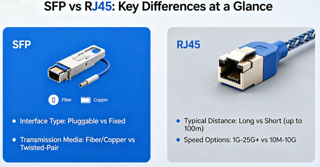
In data centers, AOCs are a convenient option for connecting racks within the same row or across adjacent rows. They are fully plug-and-play at the qsfp to rj45 interface, avoiding the need to match separate optical modules and patch cords, which simplifies purchasing, cabling design and day-to-day maintenance.
3. Multimode Fiber (MMF) with MPO
Multimode fiber (MMF) combined with MPO connectors is a key technology for short-reach parallel optics inside the data hall. Common OM3, OM4 and OM5 grades can support 40G, 100G, 200G and 400G over tens to hundreds of meters, depending on the specific standard and link budget.
MPO-12 and MPO-16 connectors bundle many fibers into a single plug, making them ideal for high-density backbone links between patch panels, structured cabling and high-port-count switches. For QSFP connectors mated to modules using parallel optical interfaces such as SR4 or SR8, MMF with MPO is often the default choice because it simplifies large fan-out and trunking architectures.
4. Single-Mode Fiber (SMF) with LC
Single-mode fiber (SMF) is used when links must span longer distances—starting at a few kilometers and extending to 10 km, 40 km, 80 km or more. It is usually paired with LC duplex connectors and long-reach QSFP standards such as LR, ER or ZR.
These connections are common between buildings, across large campuses and in metro or backbone networks. When QSFP transceivers use WDM or other long-haul optics, SMF with LC is typically the standard pairing, providing long-distance reach while maintaining full line-rate performance at the QSFP connector on the equipment side.
5. How Media Choice Interacts with QSFP Cages & Connectors
Regardless of whether the link uses DAC, AOC, MMF or SMF, everything ultimately terminates at the same hardware interface on the host system: the QSFP connector and its cage. A well-designed QSFP cage has to balance EMI shielding, thermal behavior, mechanical strength and mating durability so that all supported cable and module types perform reliably over the full product lifetime.
GLGNET QSFP cages and connectors are developed in line with relevant SFF/MSA specifications and meet RoHS and ELV environmental requirements. They are qualified with a wide range of copper DAC, AOC and optical modules, enabling equipment manufacturers to standardize on a single GLGNET QSFP connector platform. This approach lets designers move flexibly between copper and fiber solutions—based on distance, cost and power targets—without having to redesign the front panel or change the underlying connector layout.
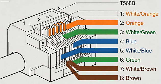
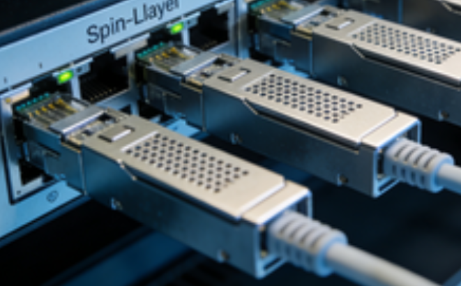
QSFP to RJ45 & Mechanical Interface Variations
Beyond data rate and cabling, the way a QSFP to RJ45 connector and its cage are built has a major influence on signal integrity, EMI performance and overall system layout. Below is a concise look at the key mechanical aspects—and how GLGNET supports them in real designs.
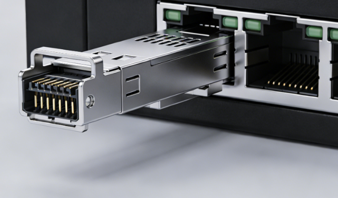
1. zQSFP+ & High-Performance Cage Designs
zQSFP+ can be seen as an upgraded version of the classic QSFP+ interface. It keeps a compatible mechanical outline, but the connector and cage are optimized for tighter signal integrity and better EMI control. This allows the same footprint to support not only 40G QSFP+ modules, but also higher-speed interfaces like QSFP28 (100G) and QSFP56 (200G).
GLGNET’s high-performance QSFP / zQSFP+ cage solutions are designed for exactly these kinds of upgrades. They help customers push bandwidth on familiar QSFP connector footprints, while managing cost, risk and re-use of existing mechanical designs.
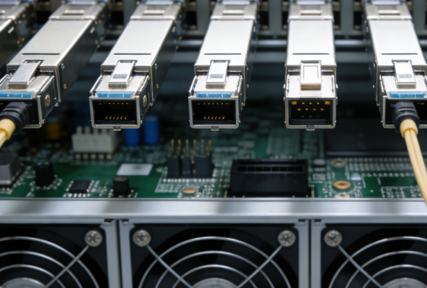
2. QSFP Cages, Housings & Port Configurations
QSFP cages are offered in a variety of layouts, from simple single ports to very high-density multi-port blocks. Common options include:
Single cages – one QSFP connector per cage, easy to place and route.
Ganged cages – several ports in one horizontal row, good for clean cabling and tidy front panels.
Stacked cages – multiple rows of ports, ideal when you need maximum density in a limited height.
Key mechanical details—such as cage rigidity, EMI gaskets and press-fit pin design—directly affect shielding, assembly robustness and long-term reliability.
GLGNET provides a wide QSFP cage portfolio including 1×1, 1×3, 1×4, 2×1, 2×2, 2×3 and 2×6 configurations for QSFP / QSFP28, in both single and stacked styles. Options with integrated QSFP connectors, heat sinks and light pipes give OEMs the flexibility to balance port density, PCB routing and front-panel space, all while staying on a consistent GLGNET QSFP connector platform.
3. Thermal Management & Light Pipes
As QSFP modules evolve from 40G and 100G to 200G, 400G and 800G, power and heat density naturally rise. Dense QSFP areas need well-managed airflow and effective heatsinking; without that, modules can overheat and suffer from throttling or unstable operation.
To address this, GLGNET QSFP cages support several thermal options, including top-mounted or integrated heat sinks and cage geometries that work with the system’s airflow direction. Light pipes can be added to guide LED status from the module or PCB to the front panel, so engineers can quickly check link and activity status for each QSFP connector during operation and troubleshooting.
By combining these elements—optimized cages, flexible port configurations, thermal options and light pipes—GLGNET helps customers build QSFP connector solutions that are not only high-speed and high-density, but also robust, maintainable and ready for 40G through 800G applications.
GLGNET QSFP Cage & Connector Solutions
GLGNET offers a unified, future-ready QSFP cage and connector platform from 40G up to 800G, covering QSFP+, QSFP28, QSFP56, QSFP-DD, QSFP112 and QSFP-DD800. Our solutions are built for high-speed systems, with a focus on signal integrity, EMI performance and reliable press-fit mounting, and they comply with major standards such as MSA, SFF, RoHS and ELV. With flexible options—single, ganged and stacked cages, plus selectable heat sinks, light pipes and EMI gaskets—customers can adapt the QSFP front panel to their own switch or server design without starting from scratch.
GLGNET QSFP products are already deployed in internet data centers, AI and cloud clusters, telecom equipment and enterprise networking platforms. Whether you’re designing a new high-speed system or migrating from 40G/100G to 200G, 400G or 800G, GLGNET can support you from early design through to mass production. For design support, samples or a fast quotation, simply visit the GLGNET QSFP product page and contact our team.
https://www.glgnet.biz/articledetail/what-is-the-difference-between-sff-and-sfp-module.html
https://www.glgnet.biz/articledetail/what-are-msa-standards-and-msa-sfp.html
Conclusion
Choosing the “right” QSFP solution is ultimately about matching three elements: the generation and lane speed (40G to 800G), the cable or fiber type (DAC, AOC, MMF, SMF), and a cage/connector design that can handle signal integrity, EMI and thermal requirements in a real chassis. When these parts are aligned, you get links that are fast, reliable and easy to scale.