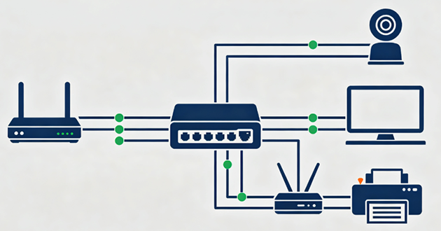
Introduction:
In network cabling and Ethernet connections, the RJ45 connector is one of the most commonly used interfaces.
Whether it's a home network, an office or a data center, RJ45 plays a vital role. However,
to ensure the stability and efficiency of the network connection, the correct RJ45 pin arrangement (Pinout) is key.
This article will detail the RJ45 pin arrangement method to help you easily complete the network cabling.
1.What is RJ45 pinout?
The RJ45 pinout refers to the insertion of the eight wires in the twisted pair into the pins of the RJ45 connector in a specific order.
The correct pinout ensures the stability and compatibility of data transmission. There are two common pinout standards:
T568A and T568B. The main difference between the two standards is the difference in line order, but they are functionally fully compatible.
2. RJ45 pinout standards
The Rj45 pin standard defines the function of each pin and how the signal is transmitted. Rj45 is usually used in Ethernet cables,
it follows the two pin standards (T568A and T568B) there is a part of the difference between the two pin standards,
although they are eight numbers, but also corresponding to different colors, but these colors are not the same function,
which is worth our attention.
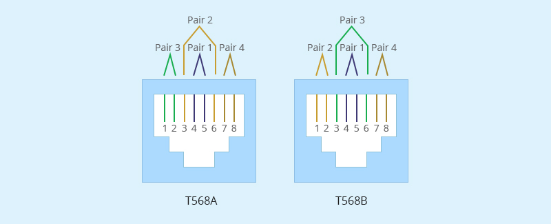
2.1 T568A standard
T568A is a very common pin standard, mainly used in North America and some international standards, rj45 pinout number 1-8,
there are corresponding colors between them, and the signal function is different, which white green, green is used to send data,
and white orange and orange are mainly used to receive data. The rest of the color has not been used for the time being,
before the pin, we first compare the color and number, understand the function of the corresponding number color,
if still can not distinguish, you can search the corresponding color online, the specific T568A standard.
That way the rj45 pinout will not be easy to mistake.
2.2 T568B standard
T568B is another common pin standard that is widely used worldwide, and this standard has a larger application range than T568A.
T568B and T568A, there are 8 numbers, the difference is that their numbers correspond to different colors,
such as white orange and orange in T568A is used to receive data, and in T568B is used to send data,
rj45 pinout number is different, the color is different, it is easy to identify errors.
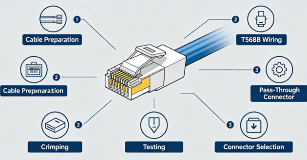
3.How to correctly arrange RJ45 pinout?
To properly sequence the RJ45 pins, you need to follow a specific cabling standard, namely T568A or T568B.
These standards define the order in which the individual cables inside the Ethernet cable are connected to the RJ45 connector.
3.1 Selective wiring standard
There are two main cabling standards for arranging the RJ45 pinout in order: T568A and T568B.
Just now we understand the difference between the two rj45 pin standards, in the correct arrangement of the rj45 pinout order,
we must first choose one of the standards, the two standards are the same in function, but T568B is more commonly used
in modern networks. If we choose a standard, we need to keep it consistent across the network to avoid problems.
3.2 Prepare cables and connectors
After selecting the standard, we need to start preparing cables and connectors, the tools we need are mainly Ethernet
cables (such as Cat5, Cat5e, Cat6, etc.), RJ45 connectors, crimping pliers, wire strippers, cable tester (optional, for verification).
With the tool ready, start peeling the outer skin of the Ethernet cable about 1-2 inches, exposing the inner cable,
then unplug the cable pair and arrange it according to the standard we selected earlier.
3.3 Arranging Cables
The two rj45 pin standards arrangement cable sequence is different, T568A number 1-8 arrangement color standard
is white green, green, white orange, blue, white blue, orange, white brown, brown, T568B number 1-8 arrangement color standard
is white orange, orange, white green, blue, white blue, green, white brown, brown. At the beginning of the selection of
any standard, the corresponding standard number and color are arranged.
3.4 Insert the cable into the RJ45 connector
After arranging the cables, insert them into the rj45 connector. First trim the cable, make sure that the cable is neat and
trimmed to a consistent length (about 0.5 inches), not long and short, and maintain unity. Carefully insert the cables into
the rj45 in the correct order (from pins 1 to 8). After inserting the cables, carefully check that the cables are
in the correct order to avoid errors, and ensure that the cables are fully inserted into the rj45 connector so that
you can proceed to the next step.
3.5 Crimp connectors
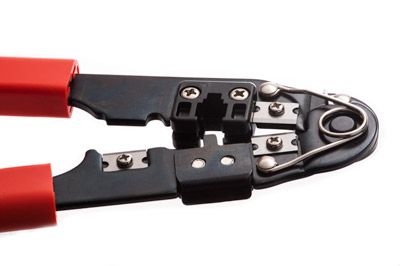
After confirming that the preceding steps are correct, place the RJ45 connector in the crimping pliers and squeeze
the crimping pliers to secure the cable to the connector. Ensure that the connector is firmly crimped and the cable is properly secured.
3.6 Testing Cables
Use a cable tester to verify that the cable is connected correctly and that all pins are working correctly.
If the cable tester shows no errors, the RJ45 pin are in the correct order. If there is an error, it is a problem with
the previous step, repeat the above steps to eliminate the error.
The last step is to connect the other end, the other end is also according to the above steps of the rj45 pin.
4.Rj45 pin must pay attention to Straight-through Cable and Crossover Cable
4.1 The rj45 connectors at both ends of the through cable use the same wire sequence standard, but the cross cable is different.
The T568A standard used at one end of the cross cable is used, and the T568B standard is used at the other end.
4.2 Through line signal transmission is from the sending end (TX) pin directly connected to the receiving end (RX).
The cross line is not directly connected, it is still necessary to note the difference here.
Conclusion:
RJ45 pinout is the basic skill in network cabling, mastering the correct operation method can greatly improve the stability
and performance of the network connection. Whether it is a home user or a network engineer, it is very important to
understand the T568A and T568B standards and be skilled in using tools for cabling. I hope this article can help
you easily complete the RJ45 pinout and enjoy an efficient and stable network experience!
GLGNET is a national high-tech enterprise specializing in developing. manufacturing and selling Ethernet
network & communication connectors . GLGNET is committed to providing customers with complete, reliable,
industry-leading interconnect product solutions. There are many brands that also have rj45, GLGNET is a good choice.
FAQs
1.Should I use T568B or T568A?
For most modern installations—especially in the US—T568B is recommended. It is the standard for commercial, residential, and VoIP networks. The key is consistency: choose one standard and use it on both ends of every cable. Both T568A and T568B work equally well; the only difference is the swap of the green and orange pairs.
Color Order:
T568B (Most Common)
White/Orange
Orange
White/Green
Blue
White/Blue
Green
White/Brown
Brown
T568A (Alternative)
White/Green
Green
White/Orange
Blue
White/Blue
Orange
White/Brown
Brown
Key Points to Remember:
Use T568B for most modern networks and residential cabling
Use T568A only for older government or legacy installations requiring backward compatibility
Do not mix standards on opposite ends unless you intentionally want a crossover cable
Check existing infrastructure to match current patch panels or cabling
2.Which side is pin 1 on RJ45?
Pin 1 on an RJ45 connector is located on the far left when you hold the connector with the gold pins facing away from you and the retaining clip facing down. This orientation is standard when preparing cables according to T568A or T568B wiring schemes.
How to identify pin 1:
Connector orientation: Hold the plug with the clip down and pins facing away
Pin numbering: From this view, pins are numbered 1 to 8 from left to right
Wire color: Pin 1 is usually white-orange for T568B or white-green for T568A
Female jack view: When looking into a port, pin 1 is typically on the far left or top left, depending on the orientation
3.How do I wire an RJ45 connector?
Wiring an RJ45 connector involves arranging the eight wires in the correct color-coded order—for T568B: White/Orange, Orange, White/Green, Blue, White/Blue, Green, White/Brown, Brown; or for T568A: White/Green, Green, White/Orange, Blue, White/Blue, Orange, White/Brown, Brown—inserting them fully into the plug, and securing the cable jacket for proper strain relief. The T568B standard is most commonly used in modern networks, while T568A may be applied in legacy setups. After insertion, a crimping tool locks the metal pins into the wires, and testing ensures all connections are correct.
Simplified Steps:
Expose the Wires: Remove about 2.5–3 cm of the outer cable jacket carefully, keeping the inner wires intact.
Organize the Pairs: Untwist the four pairs and line them up according to the chosen standard (T568B or T568A).
Trim and Position: Cut the wires evenly so they reach the front of the connector. Insert them fully, ensuring the jacket slides slightly into the plug.
Secure the Connection: Use a crimping tool to press the metal contacts into the wires, locking them in place.
Verify: Confirm all wires are fully seated and in order. Testing with a network cable tester helps ensure proper connectivity.
Practical Notes:
Standard Choice: Stick with one wiring standard consistently on both ends of the cable.
Strain Relief: Properly seating the cable jacket prevents future disconnections or damage.
Tools Needed: RJ45 plug, Ethernet cable (Cat5e/Cat6), wire stripper, crimping tool, optional tester.
4.What are common RJ45 wiring mistakes?
Common mistakes when wiring RJ45 connectors often involve incorrect wire arrangement, improper handling of the cable jacket, or failing to follow standards. For example, untwisting the pairs too far back can increase interference, using T568A on one end and T568B on the other creates an unintended crossover cable, and not seating the cable jacket inside the plug can leave wires exposed and prone to damage. Other frequent errors include cutting wires too short or long, using incompatible connectors for the cable type (e.g., Cat5e on Cat6), misaligning the pinout sequence, applying too much or too little crimping force, and skipping testing with a cable tester.
How to avoid these mistakes:
Always use the same standard (T568B recommended) on both ends of the cable.
Keep the untwisted wire length minimal—just enough to seat in the connector.
Make sure the cable jacket is secured inside the connector for strain relief.
Verify connectivity with a network cable tester to catch miswires before deployment.
5.What is the order of the wires for RJ45?
The most common wiring for an RJ45 connector follows the T568B standard: White/Orange, Orange, White/Green, Blue, White/Blue, Green, White/Brown, Brown. Hold the connector with the clip down and pins facing away—this order runs left to right from Pin 1 to Pin 8.
For older or specific installations, T568A can be used instead, with the green and orange pairs swapped: White/Green, Green, White/Orange, Blue, White/Blue, Orange, White/Brown, Brown.
Quick Wiring Steps:
Strip: Remove about 1 inch of the outer cable jacket.
Untwist & Arrange: Flatten and line up the wires according to your chosen standard.
Trim & Insert: Cut evenly and push all wires fully into the connector, keeping the jacket inside for strain relief.
Crimp: Secure the connection with a crimping tool.
Test: Use a cable tester to confirm all pins are properly connected.