


JGRBPG2T1034PW 1x2 10G RJ45 Connector with Integrated Magnetics and 120W Four-Pair PoE
JGRBPG2T1034PW 1x2 Magnetic RJ45 Connector Overview
A Dual-Port 10GBASE-T Interface with 18°±5° Latch-Up Geometry, Four-Pair PoE, 30 µin Gold Contacts and an LCP Housing
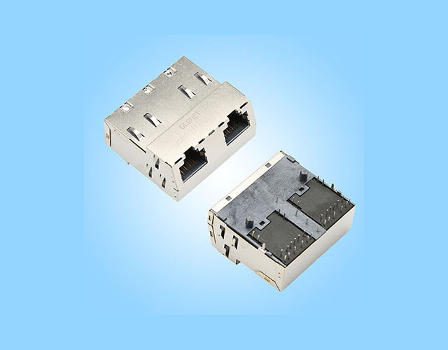
GLGNET JGRBPG2T1034PW, part number 44482-80M231, is a 1x2 10G RJ45 connector with two copper interfaces and no LEDs. This RJ45 with integrated magnetics uses an 18°±5° side-entry, latch-up structure, through-hole mounting, EMI fingers, and a 4PPoE (120W) drawing designation.
The nominal body dimensions are 36.50 × 41.10 × 19.00 mm. A glass-filled LCP housing, phosphor-bronze contacts with 30 µin mating-area gold, and a 0.2 mm copper-alloy shield define the material configuration. Operating and storage temperatures are both -40°C to +85°C.
Two 10GBASE-T Interfaces with Specified Magnetic Test Conditions
The RJ45 MagJack uses a 1:1±2% turns ratio. OCL is 120 µH minimum at 100 kHz/100 mV with 19 mA DC bias for Channels 1–4. The drawing specifies a 2250 VDC, 60-second hipot test for these channels. These are component test conditions, not equipment operating-voltage ratings.
18°±5° Latch-Up Geometry with a Defined PCB Layout
The RJ45 modular jack connector has eight RJ45 contacts and 16 PCB circuit pins per port. Coordinate all 32 circuit pins, shield connections, mounting features, cable paths, and upper-latch release with the drawing. Body dimensions exclude the complete installation clearance.
Four-Pair PoE with Dedicated PSE Connections
The schematic assigns P13 to PSE1/2, P14 to PSE3/6, P15 to PSE4/5, and P16 to PSE7/8. The PSE-pin rating is 1.15 A maximum at 57 VDC continuous. Confirm the 120W designation's port scope and simultaneous loading when setting the equipment power budget.
30 µin Gold Contacts and a Defined Assembly Process
The drawing selects 30 µin gold at the mating interface. It recommends wave soldering or through-hole reflow with a peak of 265±5°C for 10 seconds. Validate the selected board-assembly process and equipment thermal behavior.
Need a Customized RJ45 Connector Solution? Share your JGRBPG2T1034PW dual-port PHY and PoE circuits, loading requirements, PCB and enclosure drawings, quantities, and delivery date for approved documentation, sample evaluation, and quotation support.
JGRBPG2T1034PW Magnetic RJ45 Connector Specifications
Review the detailed specifications of JGRBPG2T1034PW, including its dual-port 10GBASE-T interface, four-pair PoE, 18°±5° latch-up structure, shielding, dimensions, and operating range. Materials, magnetic tests, PSE connections, and soldering conditions are detailed in the overview and datasheet.
| Parameter | Specification | Parameter | Specification |
|---|---|---|---|
| Model | JGRBPG2T1034PW | Data Rate | 10GBASE-T |
| Part Number | 44482-80M231 | PoE Support | 4PPoE (120W); Scope by Application Review |
| Port Configuration | 1x2 | LED / Light Pipe | None |
| Number of RJ45 Contacts per Port | 8 | Shielding | 0.2 mm Copper-Alloy Shield with EMI Fingers |
| Connector Type | PoE Magnetics RJ45 Connector | EMI Finger / Gasket | EMI Fingers |
| Connector Style | Side Entry, Latch Up, 18°±5° Slant | Length | 36.50 mm |
| Mounting Type | Through Hole | Width | 41.10 mm |
| Body Height | 19.00 mm | Operating Temperature | -40°C to +85°C |
Need More Technical Information?
Download the JGRBPG2T1034PW datasheet. It includes mechanical views, a recommended PCB layout, magnetic and PSE circuits, electrical test conditions, materials, and assembly requirements. Contact GLGNET for project-specific panel design and simultaneous-port power review.
Quality Certification



Advantages of JGRBPG2T1034PW Magnetic RJ45 Connector
JGRBPG2T1034PW combines two 10GBASE-T ports, an 18°±5° latch-up structure, dedicated four-pair PSE connections, and a specified 30 µin gold/LCP/copper-alloy material configuration for coordinated signal, power, enclosure, and assembly design.


Applications of JGRBPG2T1034PW Magnetic RJ45 Connector
Evaluate JGRBPG2T1034PW for dual-port 10G copper Ethernet equipment requiring four-pair PoE and angled latch-up access. Selection should account for the approved interface drawing, both-port power requirements, panel geometry, no-LED configuration, and -40°C to +85°C operating range.

Dual-Port 10G PoE Switching Equipment
A grouped interface option where two 10GBASE-T ports need to share one connector body. Review each port's PHY and PoE connections, the loading combination, and the confirmed rating scope. Check both plug-release paths and adjacent panel features in the switch enclosure.

Dual-Output PoE Interface & Injector Equipment
Can be considered for equipment combining two copper data interfaces with four-pair power connections. The 18° port approach influences the front-panel layout. Assess the source circuitry, protection, cabling, grounding, and temperature rise together with the approved connector configuration.

Industrial Network Gateways & Control Platforms
The RJ45 modular jack connector offers a dual-port option for equipment with matching 10GBASE-T, PoE, and temperature requirements. Use the specified -40°C to +85°C range for component selection, then evaluate actual enclosure temperatures and cable access under the expected installation conditions.

OEM Dual-Port Ethernet Validation Systems
Supports evaluation of a grouped connector arrangement during equipment development. Use the approved model drawing and controlled sample builds to assess both data paths, power loading, enclosure fit, and grounding. Do not assume the two ports have an unconfirmed combined power rating.
Custom RJ45 Connector
Custom magnetic RJ45 connector solutions covering dual-port 10GBASE-T structures, 18°±5° latch-up integration, four-pair PSE connections, magnetic test requirements, contact finish, shielding, and OEM/ODM manufacturing support.
Customized Magnetic RJ45 Solutions from GLGNET
As an RJ45 connector manufacturer, GLGNET helps OEM teams coordinate dual-port mechanics, magnetic interfaces, PSE connections, and manufacturing. Use JGRBPG2T1034PW, part number 44482-80M231, drawing revision A2, as the standard configuration for project review.
Dual-Port Mechanical Structure & 18°±5° Latch-Up Enclosure Integration
Review the 36.50 × 41.10 × 19.00 mm nominal body, the recommended PCB layout, all circuit and shield connections, and both plug-release paths. The drawing's 32 circuit-pin holes are distinct from its shield and fixing features. Develop the enclosure opening from the full mechanical views. Changes to the angle, footprint, or housing require a separately approved drawing.
10G Magnetic-Interface, Four-Pair PSE & Thermal Engineering Support
Share both PHY circuits, the P13–P16 power connections, loading combinations, and ambient conditions. Use the 120 µH OCL test at 19 mA bias and the 1.15 A/57 VDC continuous PSE-pin rating as specified review inputs. GLGNET offers signal-integrity and thermal-analysis capabilities. Confirm rating scope and validation conditions before changing the circuit or power configuration.
OEM & ODM Support for Specified Materials, Plating and Assembly
The standard drawing specifies glass-filled LCP, phosphor-bronze contacts with 30 µin mating-area gold, and a 0.2 mm copper-alloy shield. It recommends wave soldering or through-hole reflow at a 265±5°C peak for 10 seconds. Coordinate process validation, inspection criteria, samples, quantities, and delivery milestones. Alternative finishes, materials, or process conditions require separate engineering approval.


