


JDHA8T807-L1/L2 2x8 Gigabit RJ45 Connector with Upper-Row LEDs
JDHA8T807-L1/L2 2x8 Magnetic RJ45 Connector Overview
Sixteen Non-PoE Gigabit Ports in a 31.13 mm-Deep Housing
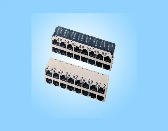
JDHA8T807-L1/L2 brings sixteen 10/100/1000BASE-T ports to the front of a single assembly. This RJ45 with integrated magnetics houses the Ethernet transformer channels for data-only links. Devices that require power use a separate supply or an appropriate powered Ethernet interface.
Upper-Row Status Indicators
The top eight jacks have green/yellow LEDs. The lower eight have no built-in LEDs. Plan lower-row status indication at the equipment level if operators need to see it at the front panel.
31.13 mm Body Depth
Check installed clearance using the side view and panel offset. The A0 drawing recommends a cutout 116.46 mm wide by 26.20 mm high, each with a ±0.13 mm tolerance.
Two Latch Directions
The upper port latches face up, and the lower port latches face down. Check finger access and plug boot clearance with all sixteen jacks populated.
Through-Hole Assembly and Shielding
Use the component-side footprint for signal and LED hole positions. Keep copper clear of the marked no-trace zone. The brass shield has EMI fingers for panel contact. The drawing recommends wave soldering at up to 260°C for a maximum of 10 seconds.
Planning a 16-Port Panel with Limited Depth? Send your enclosure and board drawings so GLGNET can review the cutout, latch access and fit.
JDHA8T807-L1/L2 2x8 Magnetic RJ45 Connector Specifications
Check the data rate, upper-row LED arrangement, mounting method and housing dimensions before selecting this jack for your PCB and front-panel design.
| Parameter | Specification | Parameter | Specification |
|---|---|---|---|
| Model | JDHA8T807-L1/L2 | Ethernet Data Rate | 10/100/1000BASE-T |
| Part Number | 130059-00111 | PoE Support | None (Data Only) |
| Port Configuration | 2x8 Stacked (16 Ports) | LED / Light Pipe | Green/Yellow LEDs on Upper Row Only |
| RJ45 Contacts per Port | 8 | Shielding | 0.2 mm Brass Shield |
| Connector Type | RJ45 Modular Jack Connector with Integrated Magnetics | EMI Finger / Gasket | EMI Fingers |
| Connector Style | Side Entry, Upper Latch Up / Lower Latch Down | Depth (A0 Side View) | 31.13 ±0.38 mm |
| Mounting Type | Through-Hole Soldering | Housing Width (Across Front) | 115.06 mm |
| Housing Height (A0 Side View) | 25.27 mm | Operating Temperature | 0°C to +70°C |
Need the Panel Cutout or PCB Footprint?
Download the JDHA8T807-L1/L2 drawing for cutout tolerances, the component-side layout and the upper-row LED circuit.
Quality Certification



Advantages of the JDHA8T807-L1/L2 2x8 Gigabit RJ45 Connector
A sixteen-port layout with a 31.13 mm body depth, upper-row LEDs and defined mechanical dimensions for data-only Ethernet designs with limited space behind the panel.


Applications of the JDHA8T807-L1/L2 2x8 Gigabit RJ45 Connector
Consider this RJ45 MagJack for equipment that groups data-only copper ports in one front-panel assembly and connects to separately powered devices.

Non-PoE Gigabit Switches
Serve wired desktops and other self-powered clients through grouped access ports. Check cable clearance when both rows are occupied.

Network Test Fixtures
Group wired endpoints for bench tests. Use upper ports for visible status and power test devices separately.

Rack-Mounted Network Appliances
Use the stated depth to check panel-to-board fit when designing a copper interface for a shallow enclosure.

Storage Network Equipment
Route copper links to independently powered storage systems. Keep patch cords accessible during servicing.
Custom RJ45 Connector Support for Data-Only Network Equipment
Review the panel opening, board footprint and upper-row LED wiring.
Integration Review for Sixteen Data Ports
As an RJ45 connector manufacturer, GLGNET can review your JDHA8T807-L1/L2 assembly against the panel opening, PCB and indicator plan. Send the target port map and state which links need front-panel indication.
Panel and Cable Access
Provide enclosure drawings to check the recommended cutout and cable boot clearance for the opposing latch directions.
Board and Indicator Interface
Share the component-side footprint and LED drive schematic for review before the first build. Include any keepout constraints.
Samples and Production Planning
Include sample quantities, board release dates and forecast demand so GLGNET can confirm the review and supply requirements.


