


JDHA6T807-L1/L2 2x6 Magnetic RJ45 Connector with Upper-Row LEDs
JDHA6T807-L1/L2 2x6 Magnetic RJ45 Connector Overview
Twelve Non-PoE Gigabit Ports with Built-In LEDs on the Upper Row
JDHA6T807-L1/L2 packs twelve 10/100/1000BASE-T ports into two rows of six. This RJ45 with integrated magnetics puts the transformer channels inside the housing. It is designed for copper Ethernet links without PoE.
The upper row has built-in green/yellow indicators, while the lower row has no LEDs. Both rows accept plugs from the front, with the upper latches facing up and the lower latches facing down.
Upper-Row Status Indication
Plan LED drive and status behavior at the board level. Check the LED circuit and the left/right color positions against the drawing.
Through-Hole PCB Footprint
Use the component-side pattern to locate the signal and LED pins. Keep copper traces clear of the marked no-trace zone.
Chassis Fit and Shield Contact
The body is 87.12 mm wide and 31.12 mm deep. The drawing shows a nominal panel opening of 88.52 by 26.20 mm. The front view separately shows a 91.00 mm span across the side EMI fingers.
Four-Pair Ethernet Magnetics
The schematic shows four transformer channels with a 1:1 turns ratio. Review the PHY interface, grounding and shield contact in the finished equipment.
Need a Customized RJ45 Connector Solution? Share your PCB footprint, panel cutout and LED drive requirements with GLGNET for an application review.
JDHA6T807-L1/L2 2x6 Magnetic RJ45 Connector Specifications
Check the port count, Ethernet speed, upper-row indicator placement, body dimensions and through-hole mounting details before finalizing your board and panel design.
| Parameter | Specification | Parameter | Specification |
|---|---|---|---|
| Model | JDHA6T807-L1/L2 | Ethernet Data Rate | 10/100/1000BASE-T |
| Part Number | 130058-00711 | PoE Support | None (Non-PoE) |
| Port Configuration | 2x6 Stacked (12 Ports) | LED / Light Pipe | Green/Yellow LEDs, Upper Row Only |
| RJ45 Contacts per Port | 8 | Shielding | 0.2 mm Copper Alloy Shield |
| Connector Type | RJ45 Modular Jack Connector with Integrated Magnetics | EMI Finger / Gasket | EMI Fingers |
| Connector Style | Side Entry, Upper Latch Up / Lower Latch Down | Body Depth (Front to Back) | 31.12 mm |
| Mounting Type | Through Hole | Body Width (Across Front) | 87.12 mm |
| Body Height (A0 Drawing) | 25.27 mm | Operating Temperature | 0°C to +70°C |
Need the PCB Layout and LED Circuit?
Download the JDHA6T807-L1/L2 datasheet for the panel cutout, PCB hole pattern, Ethernet magnetics and LED connections.
Quality Certification



Advantages of the JDHA6T807-L1/L2 2x6 Gigabit RJ45 Connector
The stacked housing combines twelve non-PoE ports with upper-row indicators, a through-hole footprint and EMI fingers for contact at the chassis opening.


Applications of the JDHA6T807-L1/L2 2x6 Gigabit Ethernet RJ45 Connector
Evaluate this RJ45 MagJack for multiport equipment that uses non-PoE copper links and needs front-panel indicators on the upper row.

Non-PoE Gigabit Switches
Group twelve copper ports on one panel. Plan how to display status for the lower row.

Rack-Mounted Network Appliances
Use the two-row layout for front-facing copper I/O. Allow plug release clearance above and below the assembly.

Wired Network Gateways
Bring multiple local Ethernet connections to one panel and map the upper-row indicators to the equipment's status logic.

Ethernet Test Equipment
Place multiple test connections at the panel. Check access for repeated plug changes and label both rows.
Custom RJ45 Connector Solutions for Stacked Gigabit Designs
Review panel fit, LED drive and board layout with GLGNET.
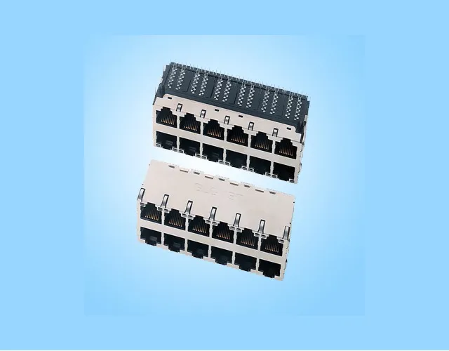
Customized Magnetic RJ45 Solutions from GLGNET
As an RJ45 connector manufacturer, GLGNET can review the standard part against your board layout and panel geometry. Share your required indicator behavior and explain which parts of the footprint or interface need to change.
PCB and Panel Fit Review
Provide the hole pattern, board edge and cutout so GLGNET can assess mounting fit and plug clearance.
LED and Electrical Interface Review
Share the LED drive scheme, PHY and grounding design to review pin assignments, indicator behavior and shield contact.
OEM and ODM Manufacturing Support
Provide prototype quantities, verification requirements and expected volume to assess project feasibility and timing.


