RJ45 connectors come in various forms, each tailored for specific network setups and installation needs. From keystone jacks used in structured cabling to field-terminated plugs for on-site terminations, every type offers unique benefits and trade-offs in terms of performance, durability, and ease of installation. Understanding these differences is key to building a reliable network that meets your bandwidth and environmental requirements. This article explores the main RJ45 connector types, explains their ideal use cases, and offers practical guidance on how to choose the most suitable option for your project.
What Are the Different Types of RJ45 Connectors
What Is an RJ45 Connector
Shielded vs. Unshielded RJ45 Jack Connectors
-Unshielded (UTP) RJ45 Connectors
-Shielded (STP/FTP) RJ45 Connectors
Pass-Through vs. Non-Pass-Through RJ45 Connectors
-Non-Pass-Through RJ45 Jack Connectors
-Pass-Through RJ45 Connectors
RJ45 Jack Connector Category Ratings
Other RJ45 Connector Variants
-Tool-less RJ45 Connectors
-Field-Terminated RJ45 Connectors
-RJ45 Keystone Jacks
-RJ45 Inline Couplers / Connectors
How to Choose the Right RJ45 Connector
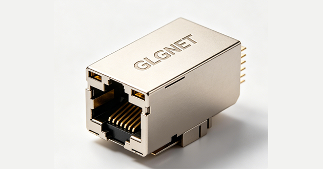
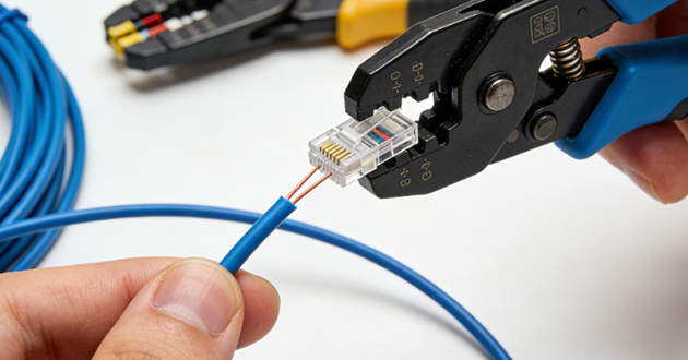
What Is an RJ45 Connector?
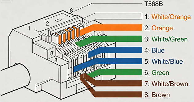
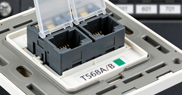
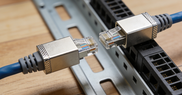
An RJ45 connector is a type of 8P8C (eight positions, eight contacts) modular interface designed to attach Ethernet cables to networking hardware such as switches, routers, and computers. It is typically made with a transparent plastic body and fitted with eight precision gold-plated pins that help maintain stable, low-loss signal transmission. Widely used in residential internet setups, corporate LAN infrastructures, industrial control systems, and IoT applications, the RJ45 plays a critical role in establishing reliable wired connections. Cable terminations are usually made according to T568A or T568B wiring schemes, ensuring proper pairing and interoperability across devices.
If you’d like to learn the step-by-step process of attaching an RJ45 connector to a cable, follow our practical guide on how to connect an RJ45 connector.
Quick Reference Table: Types of RJ45 Connectors and Their Uses
|
Category |
Type |
Key Features |
Best For |
|
Shielding |
Unshielded (UTP) RJ45 |
No metal shielding, cost-effective |
Home/office networks with low EMI |
|
Shielded (STP/FTP) RJ45 |
Metal foil or braid for EMI protection |
Industrial or high-speed networks |
|
|
Termination |
Non-Pass-Through RJ45 |
Wires stop inside connector before crimping |
Standard patch cables |
|
Pass-Through RJ45 |
Wires extend through front for easier alignment |
DIY and error-free terminations |
|
|
Category Rating |
Cat5e RJ45 |
Up to 1 Gbps |
Standard home/office use |
|
Cat6 RJ45 |
Up to 10 Gbps (≤55m) |
Faster office networks |
|
|
Cat6a RJ45 |
Up to 10 Gbps (≤100m) |
High-speed, long-distance runs |
|
|
Cat7 RJ45 |
Fully shielded, high performance |
Data centers, industrial setups |
|
|
Other Types |
Tool-less RJ45 |
No crimping tool required |
Quick field installs |
|
Field-Terminated RJ45 |
Easy on-site termination |
Industrial/custom projects |
|
|
RJ45 Keystone Jack |
Fits wall plates/patch panels |
Structured cabling systems |
|
|
RJ45 Inline Connector |
Joins two Ethernet cables |
Cable extension/repair |
Shielded vs. Unshielded RJ45 Jack Connectors
Unshielded RJ45 jack connectors do not include any metallic foil or braid at the termination point, so protection against interference comes entirely from the precision of the twisted-pair construction and the quality of the cable’s installation. They are lightweight, affordable, and straightforward to assemble, which makes them the go-to choice for home networks, small business LANs, and other spaces where electromagnetic noise is minimal. In electrically demanding settings—such as near large motors, welding gear, or tightly packed trays carrying multiple high-speed cables—UTP connectors can be more prone to near-end crosstalk (NEXT) and alien crosstalk from adjacent runs. In these cases, careful cable management, increased spacing from power lines, and smaller bundle sizes are often required to preserve network performance.
Shielded (STP/FTP) RJ45 Connectors
Shielded versions add a conductive barrier—such as overall foil (F/UTP), foil on each pair (U/FTP), or a braid combined with foil (S/FTP)—to reduce external electromagnetic interference and minimize pair-to-pair coupling. When used with shielded cabling, they can deliver excellent noise suppression, making them well-suited for high-frequency and high-speed environments like 10GBASE-T uplinks, IPTV distribution systems, and precision industrial control networks. To perform as intended, the shield must be terminated with full 360-degree contact to the connector housing, and grounding continuity must be maintained throughout the link. Improper terminations—such as leaving shield “pigtails” or failing to bond correctly—can create unwanted current loops and compromise performance. While they excel in noisy or high-density environments, shielded connectors are typically more expensive, require more care during installation, and add bulk to the cable, which can limit flexibility in tight spaces.
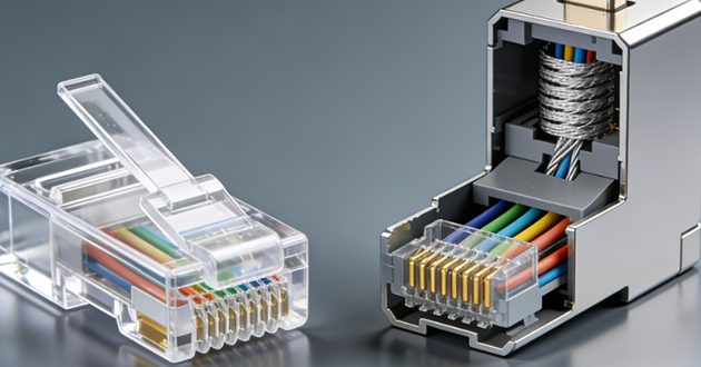
Pass-Through vs. Non-Pass-Through RJ45 Connectors
Non-Pass-Through RJ45 Jack Connectors
This is the conventional termination style: each conductor is cut to its exact length, placed into the rj45 jack connector, and then crimped in place. Since the conductor ends stop inside the connector housing rather than protruding, the internal geometry is more repeatable, helping maintain impedance control and stable return-loss characteristics—particularly valuable for higher-category cabling. Many quality non-pass-through plugs incorporate load bars or staggered entry paths, keeping pair lay tight and limiting untwist, which helps reduce near-end crosstalk (NEXT). They’re compatible with standard crimp dies, which makes them a mainstay for factory-assembled patch cords.
Field considerations
Verification – With wire ends hidden, installers must rely on disciplined pre-staging or continuity testing to confirm T568A/B wiring before crimping.
Pass-Through RJ45 Connectors
In this design, each conductor passes completely through the front of the rj45 connector before crimping and trimming flush. This makes the wiring order visible, greatly reducing the risk of pinout errors and speeding on-site terminations—ideal for field technicians making custom lengths or MPTL (Modular Plug-Terminated Link) runs to devices like cameras or wireless APs.
Field considerations
Cut quality – Always use a dedicated pass-through crimper that both crimps and shears conductors perfectly flush; even slight protrusions can act as small antennas, degrading return loss or damaging mating contacts.
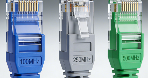
RJ45 Jack Connector Category Ratings
To ensure optimal performance, RJ45 connectors should meet — and ideally exceed — the category rating of the cable they are paired with. If any single component in the link is rated lower, the network will perform only to that weakest specification.
Cat5e — Rated for 100 MHz, this category supports Gigabit Ethernet (1 GbE) across most standard lengths. While still found in many basic networks, it is gradually being replaced by higher-rated options in new installations.
Other RJ45 Connector Variants
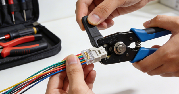
Tool-less RJ45 Connectors
Tool-less RJ45 connectors rely on IDC (Insulation Displacement Contact) caps or cam/lever-actuated mechanisms to seat conductors without the use of a crimping tool. They’re well-suited for rapid network expansions, workstation relocations, or temporary setups where deployment time is critical. Performance, however, is highly dependent on precise cable compatibility—matching the connector to the conductor type (solid vs. stranded), gauge (commonly 23–26 AWG), and outer diameter is essential. A mismatch can lead to suboptimal conductor seating, increased near-end crosstalk (NEXT), and impaired high-frequency performance, particularly in Category 6A channels operating at 500 MHz.
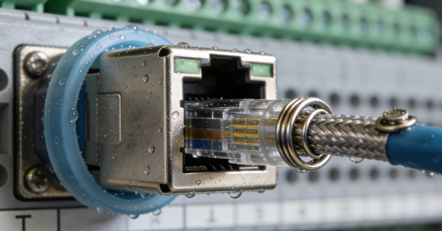
Field-Terminated RJ45 Connectors
Built for robust, on-site terminations, these rj45 jack connectors typically incorporate metal housings, integrated strain relief, and 360° shield termination to maximize EMI/RFI suppression. They are a preferred choice for Modular Plug Terminated Link (MPTL) installations, where the cable terminates directly to devices like wireless APs, IP surveillance cameras, or automation controllers. This eliminates intermediate outlets but reduces tolerance for installation errors—maintaining minimal pair untwist, precise conductor alignment, and shield continuity is critical to keeping the entire channel within its performance specification.
RJ45 Keystone Jacks
As foundational components in structured cabling, keystone jacks are used in wall outlets, patch panels, and consolidation points. Higher-quality models feature pair management bars, precision IDC contacts, and T568A/B color-coded guides to optimize conductor placement and preserve impedance balance. For shielded deployments, low-resistance bonding between jack, panel, and grounding infrastructure is essential to prevent shield breaks, which can otherwise degrade common-mode noise rejection and cause certification failures under ANSI/TIA standards.
RJ45 Inline Couplers / Connectors
Inline couplers enable two cable segments to be joined, allowing quick repairs or ad-hoc extensions without pulling new cable. In high-performance networks, they must match or exceed the category rating of the existing channel and maintain full shielding in shielded installations. While convenient, each additional mated interface introduces insertion loss, return loss, and added crosstalk. As a best practice, limit use to one coupler per channel and treat them as a short-term contingency rather than a permanent design choice—especially in 10GBASE-T environments where margin is tighter.
How to Choose the Right RJ45 Connector
The best RJ45 connector for your project depends on where and how it will be used. For fixed structured cabling, keystone jacks combined with patch panels provide a robust, certifiable, and easily maintainable backbone. When connecting directly to devices such as IP cameras or wireless access points, field-terminated plugs deliver on-site adaptability—so long as you preserve proper pair alignment and shielding continuity. Tool-less designs work well for rapid installations but require careful matching of cable type, conductor gauge, and jacket diameter to avoid compromising performance. Inline couplers should remain a last resort for repairs or temporary extensions, as each additional junction increases signal loss and can undermine compliance. In every case, select a connector that aligns with your cable’s category rating, shielding needs, and environmental conditions to ensure the entire link meets performance standards from the outset.
https://www.glgnet.biz/articledetail/what-are-the-applications-of-rj45-connectors.html
Conclusion
In the end, your choice should balance performance, durability, and practicality. By carefully matching the connector’s category rating, shielding, and termination style to the cable type and installation environment, you create a network that not only meets today’s bandwidth demands but remains reliable and standards-compliant well into the future.