Whether you're building a home network, upgrading office infrastructure, or simply repairing a damaged Ethernet cable, knowing how to properly connect an RJ45 connector is an essential skill.
In this guide, we’ll walk you through everything you need to know—from the tools required and wiring standards to the step-by-step connection process, crimping techniques, and final testing—to help you create a reliable and high-performance Ethernet connection.
-What Is an RJ45 Connector and How Does It Work ?
-Tools You Need to Connect an RJ45 Jack Connector
-Choosing the Right Wiring Standard for RJ45 Connector (T568A vs T568B)
-Step-by-Step Guide: How to Connect an RJ45 Jack Connector Properly
-How to Crimp an RJ45 Connector Correctly
-How to Test an RJ45 Jack Connector After Crimping
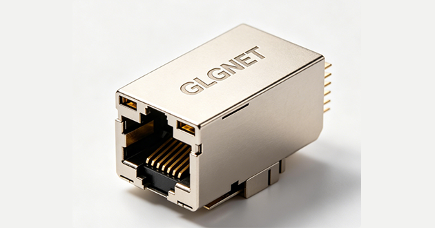
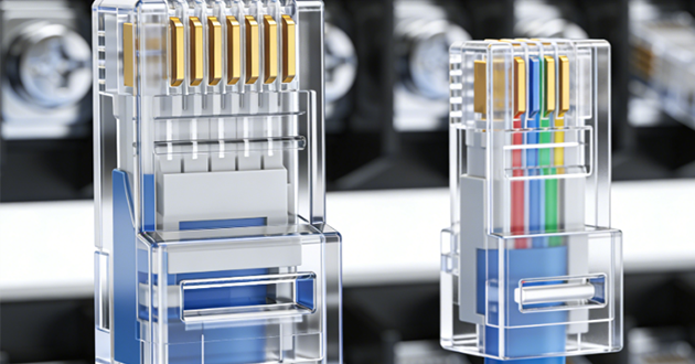
What Is an RJ45 Connector and How Does It Work ?
An RJ45 connector is a standardized modular plug with eight positions and eight contacts (8P8C), commonly used to terminate twisted-pair Ethernet cables. It serves as the interface between network wiring and devices like routers, switches, computers, and IP-based hardware, enabling fast and reliable data transmission across local networks.
While it shares a similar appearance with the smaller RJ11 telephone connector, the RJ45 supports more conductors, making it capable of handling higher bandwidth requirements. This distinction makes it ideal for modern digital communications where speed and signal integrity are critical.
If you’d like to explore the RJ45 connector in greater depth — including its variations, applications, and detailed wiring guidance — check out our comprehensive 2025 RJ45 Connector Guide for more insights.
Widely adopted in both residential and commercial structured cabling systems, RJ45 jack connectors are integral to applications ranging from smart home setups to large-scale data centers. Their global standardization, affordability, and ease of use have cemented their role as a core component in today’s wired networking infrastructure.
Tools You Need to Connect an RJ45 Jack Connector
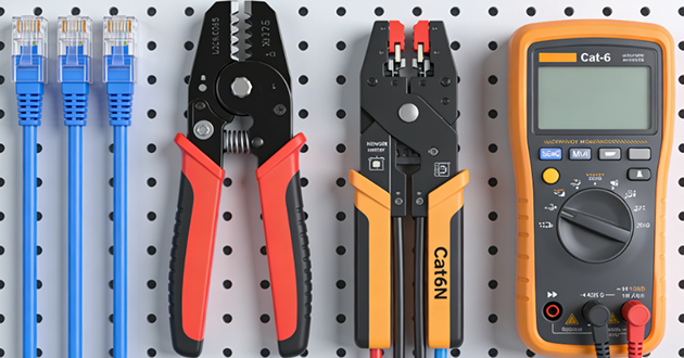
Before you begin wiring an RJ45 jack connector, it’s important to gather the right set of tools. Each item contributes to the overall accuracy, durability, and performance of your network cable. Whether you're a first-time DIY user or handling small-scale installations, having a dedicated RJ45 connector tool kit can simplify the entire process and reduce setup errors.
Below is a breakdown of the essential tools and their specific functions:
|
Tool / Material |
Purpose |
|
RJ45 Connectors |
Plug ends for Ethernet cables; available in UTP or STP types |
|
Ethernet Cable |
Cat5e, Cat6, or higher; used for network data transmission |
|
Crimping Tool |
Secures the connector onto the cable |
|
Wire Stripper |
Removes the outer cable jacket cleanly |
|
Cable Tester |
Checks wiring order and connection status |
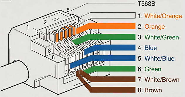
Choosing the Right Wiring Standard for RJ45 Connector (T568A vs T568B)
When connecting an RJ45 connector, selecting the correct wiring standard ensures consistent performance and compatibility. The two commonly used configurations are T568A and T568B, which follow the same pairing logic but arrange the colored wires differently inside the connector.
T568A is often used in home networks and some government installations, while T568B has become the default choice in commercial and industrial environments due to its widespread adoption.
In most cases, both ends of the cable should follow the same standard—typically T568B—to form a straight-through connection. However, if you wire T568A on one end and T568B on the other, the result is a crossover cable, useful for connecting two similar devices (e.g., two PCs) without a hub or switch.
To minimize wiring errors and ensure proper pin alignment, always refer to a color-coded guide during the termination process.
Step-by-Step Guide: How to Connect an RJ45 Jack Connector Properly
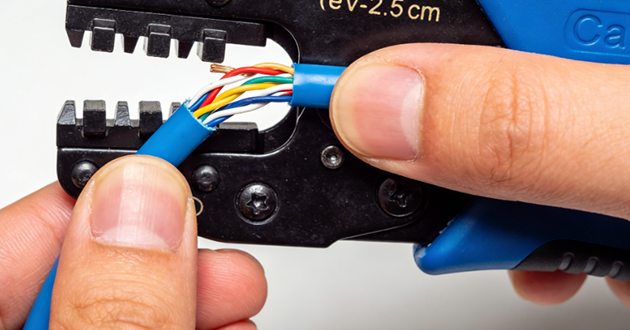
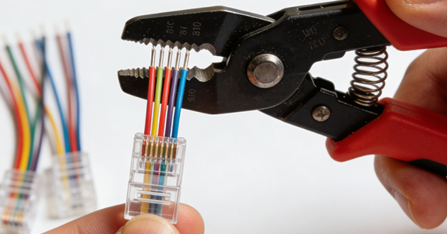
How to Strip Cable Jacket for an RJ45 Connector
Use a wire stripper to remove about 1 to 1.5 inches (2.5–3.5 cm) of the outer insulation from the Ethernet cable. Be careful not to damage the wires inside. After stripping, you should see four twisted pairs, totaling eight individual wires.
How to Untwist and Straighten Wires for an RJ45 Connector
Separate the four wire pairs and untwist each pair gently. Then straighten all eight wires using your fingers or a flat surface, so they are neat and easier to insert into the connector.
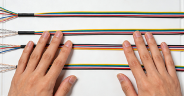
How to Arrange Wires in the Correct RJ45 Connector Sequence
Arrange the wires in the correct color order based on the T568A or T568B wiring standard. The wires should be lined up flat and parallel, without overlapping or crossing.
How to Trim Wires Evenly Before Inserting into an RJ45 Connector
Use a cutter to trim the wires to the same length, leaving about 0.5 inches (1.3 cm) exposed. Make sure the ends are even so they can all make contact with the pins inside the connector.
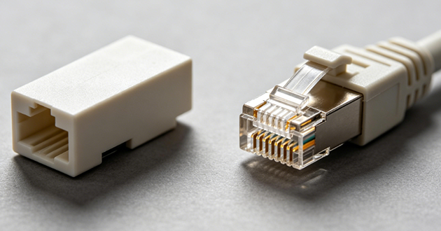
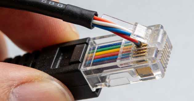
How to Insert Wires into an RJ45 Connector Correctly
Hold the RJ45 jack connector with the clip facing down. Gently slide the wires into the connector, guiding each one into its channel. Push the wires in until all tips reach the front edge and the cable jacket is slightly inside the connector for strain relief.
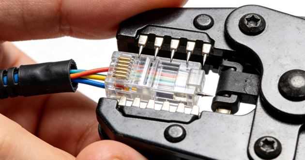
How to Crimp the RJ45 Connector Securely
Insert the connector into the crimping tool’s RJ45 slot. Squeeze the handles firmly until the metal pins press down into the wires and the connector is securely locked onto the cable. After crimping, check that the connector is tight and the wires are not loose.
How to Crimp an RJ45 Connector Correctly
Crimping is the final—and arguably most important—step in terminating an RJ45 connector. Done correctly, it guarantees both electrical performance and mechanical stability. Below is a guide to help you complete this step with precision and confidence.
Pre-Crimp Checklist: Ensure Proper Alignment
Before you begin crimping, take a moment to confirm the following:
The wires are arranged in the correct color order (T568A or T568B) and are flat, untangled, and aligned.
All eight conductors are fully inserted, with their tips reaching the front edge of the connector’s plastic housing.
The cable’s outer jacket extends slightly into the connector, offering strain relief and added durability.
Proper preparation here can prevent connection failures and signal issues later on.
Crimping the RJ45 Connector: Step-by-Step
Insert the prepared RJ45 connector into the crimping tool’s designated slot.
Verify that the connector is fully seated and stable.
Press the handles of the crimper firmly and evenly in a single motion—avoid applying pressure in stages.
This compresses the internal metal contacts into the copper cores of the wires, creating a solid electrical bond while anchoring the connector in place.
Once crimped, the connection should feel tight and secure, with no visible gaps or movement between the cable and plug.
Crimping Mistakes That Can Lead to Cable Failure
To ensure a reliable connection, avoid these common errors:
Wires not fully inserted: Incomplete contact may lead to intermittent connectivity or total signal loss.
Inconsistent crimp pressure: Pins may not penetrate the wires properly, resulting in poor transmission.
Over-crimping or repeated crimping: Can deform the connector or damage the internal contacts, making the cable unusable.
Taking the time to crimp with care ensures that your RJ45 connector performs reliably in any setting, whether you're building a home network or wiring an enterprise infrastructure.
How to Test an RJ45 Jack Connector After Crimping
After finishing the crimping process, it’s important to verify that the connection inside the RJ45 connector is electrically sound and correctly aligned. Even minor errors—such as one wire out of order or a loose contact—can compromise the performance of your network cable.
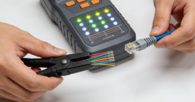
To validate your work, use a dedicated Ethernet cable tester. Plug each end of the newly terminated cable into the tester ports. Activate the device to scan each pin and check for correct signal flow and wire pairing.
During this testing process, ensure the following conditions are met:
All eight conductors are matched one-to-one from end to end (e.g., pin 1 on one end connects to pin 1 on the other).
There are no wiring faults, such as open circuits, reversed wires, or unintended bridging between pins.
The continuity check passes for each wire, indicating a complete and stable electrical path.
If any issues are detected—such as missing continuity, crossed pairs, or incorrect order—the best solution is to remove the connector, re-strip the cable, and terminate it again using a new RJ45 plug. Once re-crimped, retest the cable until all results confirm correct wiring.
Thorough testing ensures that your cable won’t cause hidden problems in a live network and saves time in diagnosing connectivity failures down the line. It’s a simple step that guarantees long-term performance and reliability.
Learn more:
https://www.glgnet.biz/articledetail/what-are-rj45-connectors-used-for.html
https://www.glgnet.biz/articledetail/how-to-wire-an-rj45-connector.html
Conclusion
Mastering the process of connecting an RJ45 connector not only improves the stability of your wired network but also gives you more control over custom installations and repairs.