Ethernet performance depends heavily on the quality of its physical connections, and the RJ45 connector is at the heart of it. A single wiring error or poor termination can cause serious network issues, from intermittent drops to complete failure. This article is to explore the correct practices for RJ45 connector installation, the most common mistakes professionals encounter, and how to ensure maximum reliability in both enterprise and home networking environments.
Understanding RJ45 Connector Wiring Standards
When setting up an RJ45 connector, you’ll need to work with one of two recognized wiring patterns: T568A and T568B. These standards dictate how the eight internal wires of an Ethernet cable should be positioned within the connector so that data signals can be transmitted reliably between devices.
T568A Standard
Under the T568A arrangement, the sequence from Pin 1 to Pin 8 is: White/Green, Green, White/Orange, Blue, White/Blue, Orange, White/Brown, and Brown.
This layout was originally promoted for residential wiring systems, which is why it often appears in older home installations. It also remains relevant in certain government or institutional networks, where adherence to ANSI/TIA specifications has historically favored T568A for compatibility with existing infrastructure. Although its role in new commercial projects has declined, it is still important whenever continuity with legacy wiring must be preserved.
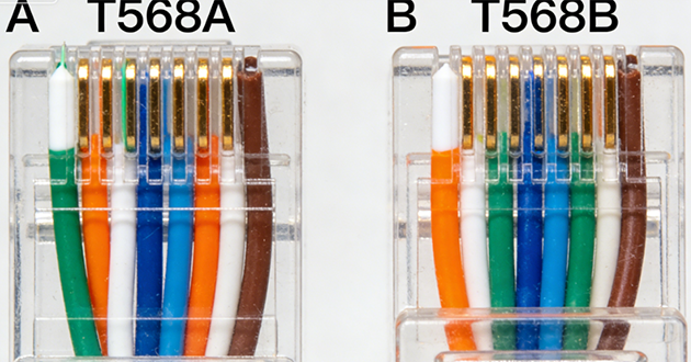
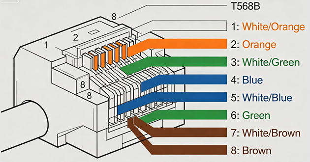
T568B Standard
In contrast, the T568B pattern reorders the green and orange pairs compared with T568A. The sequence runs: White/Orange, Orange, White/Green, Blue, White/Blue, Green, White/Brown, and Brown.
Over time, T568B has become the preferred choice for business and enterprise environments. Its popularity grew as the telecommunications sector expanded, and it remains the de facto option across most switches, routers, and structured cabling systems today. Thanks to this broad adoption, T568B is often the safest selection for new installations, especially if you want maximum compatibility with modern networking equipment.
Wiring an RJ45 Connector:Step-by-Step
With the wiring standards in mind, here’s a practical, field-tested process for attaching an RJ45 plug in a way that ensures both signal integrity and long-term durability.
Prepare the RJ45 Cable
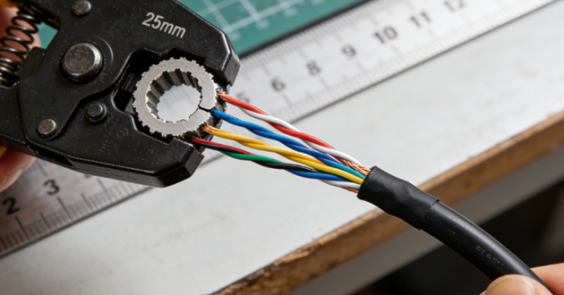
Start by stripping about 25–30 mm (1 in) of the cable’s outer jacket with a proper stripping tool, taking care not to nick the insulation of the conductors inside. Separate the four twisted pairs and fan them out gently; if the cable has a spline or ripcord, trim it flush with the jacket. It’s important to keep the twists of each pair as close as possible to the connector—ideally within 13 mm (½ in) of the termination point—to minimize crosstalk and preserve performance.
Arrange the RJ45 Connector Wires
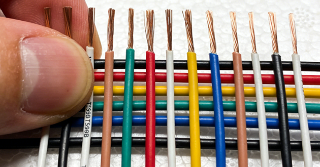
Decide whether you’re following the T568A or T568B standard, then comb the wires into the required sequence. Flatten them between your fingers and trim the ends so they are even, leaving just enough length beyond the jacket—about 6–8 mm (¼–⅜ in)—to fit neatly into the plug while still allowing the jacket to reach the strain-relief. A well-prepared bundle should look parallel and ribbon-like, with no overlaps or crossing conductors.
Insert the Wires into the RJ45 Connector
Hold the RJ45 plug with the locking tab facing down so that Pin 1 is on the left. Slide the wires into the plug in one smooth motion, keeping them in the correct order. Push firmly until the copper ends reach the very front of the connector and sit beneath the metal contacts, while also making sure the jacket is positioned inside so that the strain-relief can grip it. If you are using pass-through connectors, feed the wires all the way through, double-check the order at the tip, and then trim them flush before crimping.
Crimp the RJ45 Connector
Insert the prepared plug into a ratcheting crimp tool and press firmly until the cycle is complete. This allows the metal pins to pierce the insulation and connect with the copper conductors, while the strain-relief secures the cable jacket. Some installers prefer to add a light second squeeze to ensure the termination is set solidly. For shielded cable, make sure the shield or drain wire is also crimped according to the plug’s design. If you’re using strain-relief boots or sleeves, slide them on before you begin the crimping process.
Test the RJ45 Cable
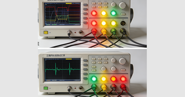
Finally, check your newly made cable with a tester to confirm proper pin-to-pin mapping (1→1 through 8→8) and verify that each pair is intact. Testing will quickly reveal issues such as opens, shorts, reversed pairs, or split pairs. On longer runs or with higher-category cabling, a more advanced tester can also evaluate performance metrics such as NEXT and return loss. If a fault shows up, the most reliable solution is to re-terminate the connector rather than trying to force a marginal crimp to work.

Common Mistakes to Avoid When Using an RJ45 Jack Connector
Even small mistakes during RJ45 jack connector termination can severely affect signal transmission, cause data loss, or make the entire connection unusable. Below are four common issues every installer should avoid:
Mixing wiring standards
A frequent error is wiring one end of the RJ45 jack connector with the T568A standard and the other with T568B. This creates a crossover cable, which is rarely required in modern Ethernet networks. For most applications, both ends must follow the same scheme—either T568A or T568B—to ensure compatibility and stable communication.
Overexposing the cable jacket
Removing too much of the cable’s outer jacket before inserting it into the RJ45 jack connector leaves the twisted pairs exposed. This weakens the connector’s strain-relief function and increases the untwisted length of the wires, which can lead to crosstalk and reduced performance. Always keep the exposed section as short as possible to maintain mechanical strength and electrical integrity.
Improper seating of conductors
If the wires are not pushed fully into the RJ45 connector, the metal contacts may fail to pierce the insulation and make proper contact with the copper cores. This often leads to intermittent connectivity, dropped packets, or open circuits on specific pins. Double-check alignment and seating before crimping.
Using low-quality tools or rj45 jack connectors
Cheap crimping tools and poorly manufactured RJ45 jack connectors often cause unreliable terminations. Substandard connectors may have weak contacts that degrade quickly, while low-quality crimpers apply uneven pressure. For long-term performance, always use certified RJ45 connectors and professional-grade crimping tools.
Read more
https://www.glgnet.biz/articledetail/are-rj45-connectors-the-same-for-cat5-and-cat6.html
Conclusion
In summary, the reliability of an Ethernet connection is only as strong as the RJ45 connector termination. By avoiding mistakes such as mismatched wiring standards, overexposing the cable jacket, improper conductor seating, and the use of substandard tools, installers can significantly improve both performance and durability. Attention to these details ensures stable data transmission and minimizes costly troubleshooting in the future.