In this guide, we will explain what a female RJ45 connector is, which tools are commonly used, how to install it step by step, how to choose between T568A and T568B, and how to test the connector after installation. We will also cover common mistakes that can lead to poor contact, unstable network speed, or failed cable testing.
What Is a Female RJ45 Connector?
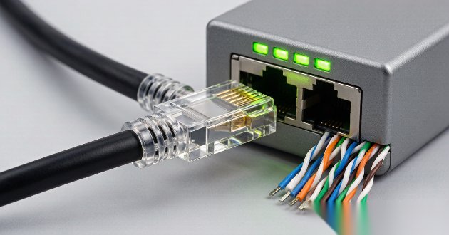
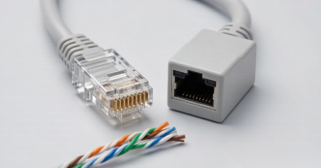
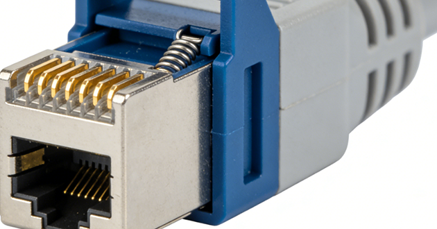
A female RJ45 data connector is the socket side of an Ethernet connection, designed to receive a male RJ45 plug and provide a stable network interface. It is commonly used in wall outlets, patch panels, data cabinets, security systems, industrial controllers, and network equipment such as routers, switches, gateways, and PoE devices. Depending on the design, it may be installed by punch-down termination, a tool-less structure, or directly mounted on a PCB for equipment applications.

What Tool Is Used to Attach RJ45 Connectors?
1.Professional Tools for Female RJ45 Connector Installation
Explain that the correct tool depends on the connector type. For most female RJ45 connectors, the common tools include:
Punch-down tool
Keystone jack termination tool
RJ45 modular jack termination tool
Wire stripper
Cable cutter
Cable tester
Small screwdriver, if required by the connector structure

2.Punch-Down Tool vs Crimping Tool
This section is important because many users confuse female RJ45 connectors with male RJ45 plugs.
Tool | Mainly Used For | Suitable Connector |
Punch-down tool | Pressing wires into IDC terminals | Female RJ45 keystone jack / patch panel |
Crimping tool | Crimping plug contacts onto cable conductors | Male RJ45 plug |
Tool-less termination cap | Pressing wires into jack without separate punch-down tool | Tool-less female RJ45 jack |
Cable tester | Checking continuity and wire sequence | Both male and female RJ45 connections |
How Do You Install an RJ45 Female Connector?
Step 1: Prepare the Cable, Connector, and Installation Tool
Before starting the installation, make sure the female RJ45 data connector matches the Ethernet cable you are using. For example, a Cat6 cable should ideally be paired with a Cat6-rated RJ45 jack to maintain the expected network performance. You will also need a cable stripper, cable cutter, punch-down tool or dedicated termination tool, a wiring standard guide, and a cable tester. Preparing these items in advance helps keep the installation process cleaner and reduces the chance of wiring mistakes.
Step 2: Strip the Cable Jacket Carefully
Remove only the length of outer jacket needed for termination. The goal is to expose the wire pairs without damaging the insulation or cutting into the copper conductors. Keep the twisted pairs as close as possible to the termination area, because excessive untwisting can affect signal stability, especially in Cat6 and Cat6A wiring. Avoid stripping too much cable at once, as this can make the finished connection less neat and less reliable.

Step 3: Separate the Wire Pairs and Choose the Wiring Standard
After the jacket is removed, gently separate the four twisted pairs: orange, green, blue, and brown. Do not straighten or untwist them more than necessary. Then choose the wiring standard you will follow, either T568A or T568B. Most female RJ45 connectors provide color-coded markings for both standards, so confirm the correct side of the label before placing the wires.
Step 4: Place Each Wire into the Correct IDC Slot
Position each conductor into the IDC slot that matches the selected wiring standard. At this stage, accuracy matters more than speed. Make sure every wire follows the color guide printed on the connector body, and check that the cable jacket sits close enough to the termination area to provide proper strain relief. A clean wire layout makes the next termination step easier and helps prevent loose or crossed connections.
Step 5: Terminate the Wires with a Professional Tool
Use a punch-down tool or the recommended RJ45 termination tool to press the wires firmly into the IDC contacts. The tool should push each conductor into place so the metal contacts can pierce the insulation and create a stable electrical connection. If the tool does not automatically trim the excess wire, cut the extra length neatly after termination. Before closing the cap or cover, check that all wires are fully seated and none have slipped out of position.
Step 6: Secure the Connector into the Final Mounting Position
Once the wires are terminated, close the dust cap or termination cover if the connector includes one. Then install the female RJ45 connector into its final position, such as a wall plate, patch panel, data cabinet, or equipment panel. Make sure the cable behind the connector is not sharply bent or pulled too tightly. Proper cable routing helps protect the termination point and supports long-term connection stability.
How to Install RJ45 Connector with Crimping Tool?
A crimping tool is mainly used to attach a male RJ45 plug to the end of an Ethernet cable. The process includes stripping the cable jacket, arranging the eight wires according to T568A or T568B, inserting them fully into the plug, and pressing the tool to secure both the contacts and the cable jacket.
For a female RJ45 data connector, the installation method is usually different. Most RJ45 jacks, keystone jacks, and patch panel ports use IDC terminals, so they are typically terminated with a punch-down tool, IDC termination tool, keystone jack tool, or tool-less termination cap rather than a crimping tool.
Simple Comparison: Crimping vs Punch-Down
Installation Type | Tool Used | Connector Type |
Cable end termination | Crimping tool | Male RJ45 plug |
Wall outlet termination | Punch-down tool | Female RJ45 jack |
Patch panel wiring | Punch-down tool | Female RJ45 port |
Tool-less jack installation | Termination cap | Tool-less RJ45 female connector |
T568A vs T568B: Which Wiring Standard Should You Use?
1.What Are T568A and T568B?
Explain that T568A and T568B are two recognized Ethernet wiring standards used to define the wire order inside RJ45 connectors.

2.T568A and T568B Wiring Order
Pin | T568A Wire Color | T568B Wire Color |
1 | White/Green | White/Orange |
2 | Green | Orange |
3 | White/Orange | White/Green |
4 | Blue | Blue |
5 | White/Blue | White/Blue |
6 | Orange | Green |
7 | White/Brown | White/Brown |
8 | Brown | Brown |
3.Which Standard Should You Choose?
For most Ethernet installations, the best choice is the wiring standard already used in the existing network. If the other end of the cable, patch panel, or wall outlet follows T568B, continue with T568B. If the project drawing, building specification, or customer requirement calls for T568A, then use T568A. The important point is to keep the same standard on both ends of the link. Mixing T568A and T568B on the same cable is only suitable when a crossover cable is intentionally required.
4.Is T568B Better Than T568A?
T568B is widely used in many commercial and residential network installations, but it is not inherently better than T568A. Both standards can support normal Ethernet transmission when terminated correctly. In practical installation, consistency and correct wire placement are more important than choosing one standard over the other.
How to Test an RJ45 Female Connector After Installation
1.Why Testing Is Necessary
After installation, an RJ45 female connector may look correct from the outside, but hidden problems can still exist inside the termination area. A wire may not be fully seated, a conductor may have poor contact, or the wire order may not match the selected standard. Testing helps identify issues such as open circuits, short circuits, reversed pairs, split pairs, miswired pins, poor contact, and unstable connections before the port is put into daily use.
2.Use a Network Cable Tester
A network cable tester is the most direct tool for checking the wiring result. Connect one end of the cable to the main tester, then connect the RJ45 female connector side through a patch cable or remote testing unit. Run the continuity test and check whether pins 1 to 8 appear in the correct order. If the tester shows a missing pin, wrong sequence, short circuit, or reversed pair, the connector should be opened and terminated again.

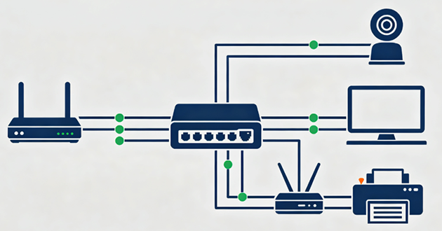
3.Test with Real Network Equipment
After the basic cable test, it is also useful to verify the connection with actual network equipment. Connect the installed RJ45 female connector to a switch, router, computer, or PoE device and check whether the link light turns on normally. A reliable connection should support stable network speed, avoid frequent disconnection, and show no obvious packet loss. If the connector is used for PoE equipment, also confirm that the device can receive power properly.
4.When to Reinstall the Connector
The connector should be reinstalled if the tester shows an incorrect pin order, the link light does not turn on, the connection speed is lower than expected, or the PoE device cannot power up. It is also a warning sign if the network disconnects when the cable is moved slightly. In these cases, re-terminating the connector is usually safer than continuing to use an unstable connection.
Common Mistakes When Installing a Female RJ45 Data Connector
Mistake 1: Mixing T568A and T568B
One common mistake is using T568A on one side of the link and T568B on the other without realizing it. This can create an unintended crossover connection and may cause network communication problems, especially when the installation is expected to be a standard straight-through link. Before terminating the wires, always confirm which wiring standard is used in the existing network and keep the same standard throughout the connection.
Mistake 2: Untwisting Too Much Cable
The twisted pair structure is designed to help reduce interference and maintain stable signal transmission. If the wire pairs are untwisted too far from the termination point, the cable may lose part of its signal performance. This is especially important for Cat6 and Cat6A installations, where excessive untwisting can increase crosstalk and affect high-speed network stability. Keep the twists as close to the IDC contacts as possible.

Mistake 3: Not Seating Wires Fully into IDC Contacts
A wire that is only partially pressed into the IDC contact may still look connected, but it can cause unstable performance during actual use. The result may be intermittent disconnection, slow network speed, or failure during cable testing. When using a punch-down tool or termination tool, make sure each conductor is firmly seated in the contact slot and does not move after termination.
Mistake 4: Using the Wrong Connector Category
Not all RJ45 female connectors are designed for the same cable category. Cat5e, Cat6, and Cat6A connectors may have different internal layouts, contact structures, and performance ratings. Using a lower-rated connector with a higher-performance cable can limit the overall network link. For best results, the cable category and connector category should match the required network speed and installation environment.
Mistake 5: Damaging the Copper Conductors
When stripping the cable jacket, cutting too deeply can nick or weaken the copper conductors inside. Even a small cut may cause the wire to break during termination or create an unreliable contact over time. Use a proper cable stripper, apply only light pressure, and check the conductors before placing them into the connector.
Mistake 6: Ignoring Shielding Requirements
For shielded Ethernet cables, the shielding structure should not be ignored during installation. If the shield is not properly connected to a shielded RJ45 connector or grounding path, the cable may not provide the expected EMI protection. In industrial equipment, PoE systems, or electrically noisy environments, the shielding design should follow the project or equipment grounding requirements.
Mistake 7: Not Testing After Installation
A finished connector can look neat but still have hidden wiring problems. Visual inspection cannot confirm continuity, pin order, short circuits, split pairs, or poor contact. Before putting the connector into service, use a cable tester to check the installation result. Testing helps catch errors early and avoids troubleshooting after the network is already in use.
FAQ About Female RJ45 Data Connector Installation
1.Can I install a female RJ45 connector without a punch-down tool?
Yes, but only if the connector is designed as a tool-less RJ45 jack. These connectors usually use a termination cap or pressure-fit structure to press the wires into place. For standard IDC-type female RJ45 connectors, a punch-down tool or dedicated termination tool is still recommended to ensure stable contact.
2.Is a female RJ45 connector the same as a keystone jack?
A keystone jack is one common type of female RJ45 connector, but they are not exactly the same. Female RJ45 connectors can also be used in patch panels, wall outlets, PCB-mounted ports, routers, switches, gateways, and other Ethernet equipment. A keystone jack mainly refers to the modular jack style used in wall plates and structured cabling systems.
3.Can I use a crimping tool for a female RJ45 connector?
In most cases, no. A crimping tool is used to attach a male RJ45 plug to the end of an Ethernet cable. A female RJ45 data connector is usually terminated with a punch-down tool, IDC termination tool, keystone jack tool, or tool-less termination cap, depending on the connector design.
4.Should I use T568A or T568B for a female RJ45 connector?
Use the same wiring standard as the rest of the network. If the existing patch panel, wall outlet, or opposite cable end uses T568B, continue with T568B. If the project specification requires T568A, follow T568A. The key is to keep the same standard across the link unless a crossover connection is intentionally needed.
5.How do I know if my RJ45 female connector is installed correctly?
Use a cable tester to check continuity, pin order, short circuits, reversed pairs, and missing connections. After that, connect the port to real network equipment such as a switch, router, computer, or PoE device. A correct installation should provide a stable link, normal network speed, and reliable power delivery when PoE is used.
Conclusion
For long-term Ethernet reliability, always choose a suitable RJ45 female connector based on the cable type, application environment, shielding requirement, and network performance needs. A properly selected and correctly installed connector can provide a more stable connection for wall outlets, patch panels, PoE devices, industrial equipment, routers, switches, and other Ethernet applications.