In the world of wired networking, the RJ45 connector is one of the most familiar and essential components. Whether you're setting up a home network, managing office cabling, or working on a data center installation, chances are you've handled one of these connectors before. More than just a plastic plug, the RJ45 connector plays a critical role in how Ethernet cables transmit and receive data between devices. Understanding its pinout, wiring standards, and the difference between straight-through and crossover cables is key to building reliable connections and avoiding network headaches.
In this guide, we'll break down everything you need to know to use RJ45 connectors effectively —— covering their structure, pin numbering, and the two main wiring standards, T568A and T568B.
What is the Pinout of an RJ45 Connector?
What is an RJ45 Connector
Does the RJ45 Connector Pinout Really Matter?
The Two Main RJ45 Connector Wiring Standards
- T568A RJ45 Connector Pinout
- T568B RJ45 Jack Connector Pinout
Straight-Through vs. Crossover RJ45 Jack Connector Cables
- Straight-Through Cable
- Crossover Cable
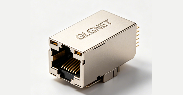
What is an RJ45 Connector
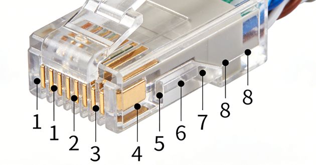
The RJ45 connector, formally classified as an 8P8C (8 Position, 8 Contact) interface, is a key component in Ethernet networking. You'll see it at the ends of network cables, acting as the bridge between the cable and devices like routers, switches, or computers. Viewed with the clip facing away, the eight pins are arranged from 1 on the left to 8 on the right, each assigned to specific data transmission or reception tasks. Using the correct pin arrangement is vital for ensuring your network runs smoothly and without interruptions.
Does the RJ45 Connector Pinout Really Matter?
It certainly does —— the way the pins are wired in an RJ45 connector directly influences the stability, speed, and overall reliability of your network. An incorrect sequence can lead to anything from occasional dropouts to a complete loss of connectivity. In high-speed Gigabit Ethernet networks, a miswired pinout may force the link to fall back to 100 Mbps or introduce packet errors that slow down data transfer. In setups using PoE (Power over Ethernet), an improper RJ45 connector pin arrangement can disrupt the power supply, which could prevent devices like security cameras or access points from functioning properly.
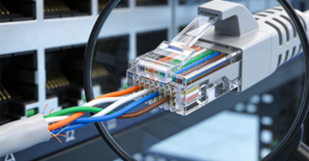
To keep your connections trouble-free, choose either the T568A or T568B wiring scheme and apply it consistently to both ends of the cable —— unless you're intentionally creating a crossover cable for a specific purpose. Before putting the cable into service, it’s a smart move to check it with a network cable tester. This ensures the RJ45 connector pinout is correctly aligned, helping you avoid costly troubleshooting later on.
The Two Main RJ45 Connector Wiring Standards
Overview of RJ45 Connector Wiring
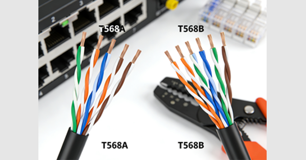
When you work with an RJ45 connector, you’ll come across two primary wiring patterns —— T568A and T568B. Both standards use eight individual wires arranged in four twisted pairs, but they differ in how the transmit (Tx) and receive (Rx) pairs are positioned. This subtle change in wire sequence doesn’t affect the physical structure of the RJ45 connector but does determine how electrical signals are sent and received across the network.
In practical terms, the choice between T568A and T568B often depends on the type of network you're building and whether you need to match existing wiring in your setup. Using the correct scheme on both ends of the cable ensures seamless communication between devices and avoids unnecessary troubleshooting.
T568A RJ45 Connector Pinout
In the T568A standard, the pin mapping for an RJ45 connector is arranged as follows:
White/Green – Transmit +
Green – Transmit –
White/Orange – Receive +
Blue – Not used in early Ethernet standards
White/Blue – Not used in early Ethernet standards
Orange – Receive –
White/Brown – Not used in early Ethernet standards
Brown – Not used in early Ethernet standards
T568A is frequently used in new network installations, particularly in residential wiring and certain government projects. One reason for its selection is its backward compatibility with older telephone cabling, which can simplify upgrades in environments where voice and data networks share infrastructure.
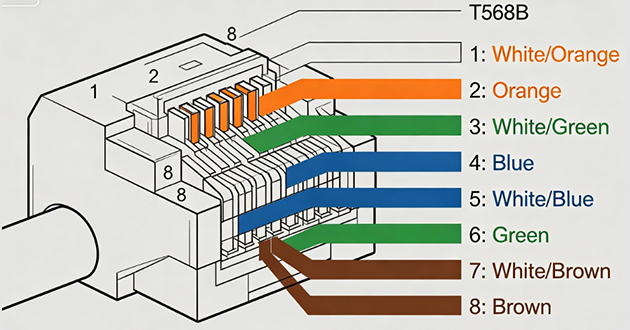
T568B RJ45 Jack Connector Pinout
The T568B layout for an RJ45 jack connector changes the position of the green and orange wire pairs while keeping the rest in the same order:
White/Orange – Transmit +
Orange – Transmit –
White/Green – Receive +
Blue – Not used in early Ethernet standards
White/Blue – Not used in early Ethernet standards
Green – Receive –
White/Brown – Not used in early Ethernet standards
Brown – Not used in early Ethernet standards
T568B is widely found in business networks, data centers, and legacy office installations. Many older Ethernet cables follow this pattern, which makes T568B the preferred option when extending or repairing an existing system. For installers, sticking to T568B in such cases avoids wiring mismatches that could lead to performance issues.
Straight-Through vs. Crossover RJ45 Jack Connector Cables
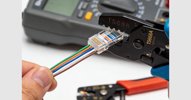
When you assemble Ethernet cables with an RJ45 jack connector, the way each end is wired determines whether the cable will be straight-through or crossover. The key difference lies in whether both RJ45 connectors follow the same wiring scheme or two different ones. This choice directly impacts how the transmit (Tx) and receive (Rx) signals align between devices, ensuring data moves in the right direction for reliable communication.
Straight-Through Cable
In a straight-through configuration, both RJ45 jack connectors at the cable's ends are wired exactly the same – either T568A ↔ T568A or T568B ↔ T568B. Each pin on one connector corresponds directly to the same pin number on the other, creating a one-to-one mapping. This type of cable is most commonly used to connect devices of different types, such as a computer to a switch, a router to a modem, or a switch to a hub. Thanks to its straightforward layout and compatibility with most networking hardware, straight-through cabling has become the standard choice for structured Ethernet installations in homes and offices.
Crossover Cable
A crossover cable uses different wiring standards on its two RJ45 jack connectors — for instance, T568A on one end and T568B on the other. This swaps the positions of the transmit and receive pairs within the cable, enabling two similar devices to communicate directly without requiring a switch or hub. In earlier networks, crossover cables were essential for connecting two computers together or linking two switches that lacked an uplink port. Even though many modern Ethernet devices now support Auto-MDI/MDIX, which automatically adjusts for cable type, keeping a crossover cable in your toolkit can still be valuable when working with older RJ45 connector-based equipment or troubleshooting specific connection scenarios.
Conclusion
The RJ45 connector may seem like a small part of your network, but its wiring and pinout have a direct impact on performance, compatibility, and stability. From knowing the difference between T568A and T568B standards to choosing the right cable type for your devices, each decision can influence the reliability of your Ethernet connection.
FAQs
1.What is the pinout for T568A?
The T568A pinout is a standard RJ45 wiring scheme that defines the order of the eight wires inside an Ethernet cable as: 1-White/Green, 2-Green, 3-White/Orange, 4-Blue, 5-White/Blue, 6-Orange, 7-White/Brown, and 8-Brown. It is commonly used in structured cabling systems and is often preferred for compatibility with older telephone wiring.
T568A Pin Configuration:
White/Green
Green
White/Orange
Blue
White/Blue
Orange
White/Brown
Brown
Key Points:
Consistency matters: Use T568A on both ends for a straight-through cable
Difference from T568B: The green and orange pairs are swapped
Compatibility: Suitable for Ethernet networks and legacy voice systems
Standard practice: Choose one wiring standard and use it consistently throughout the installation
2.Does RJ45 pinout matter?
Yes—RJ45 pinout directly affects how well a network cable performs. The specific wire order determines how signal pairs are transmitted, so using a correct standard (T568A or T568B) is essential for maintaining speed, stability, and proper connectivity.
When the pinout is correct, the twisted wire pairs stay aligned for balanced signal transmission, which minimizes interference and supports full data rates.
If the wiring order is incorrect or mixed between both ends, it can disrupt signal integrity, leading to slow speeds, intermittent connections, or even a completely non-functional cable.
It also plays an important role in Power over Ethernet (PoE). Devices like IP cameras or wireless access points rely on specific pins to receive power, so incorrect pin mapping may prevent them from working at all.
What to keep in mind:
1.Use a recognized standard (T568A or T568B) rather than mixing wire orders
2.Keep both ends of the cable consistent for proper communication
3.Incorrect pinouts can cause performance issues even if the cable appears connected
4.Proper wiring ensures both data transmission and PoE power delivery work as intended
3.How many pins does a RJ45 have?
An RJ45 connector has 8 pins and 8 positions (8P8C), meaning it supports eight individual electrical contacts used for Ethernet communication. These pins correspond to four twisted wire pairs inside the cable, which enable reliable data transmission.
Additional Details:
Pin count: 8 metal contacts inside the connector
Wire pairs: 4 twisted pairs used for signal transmission
Wiring standards: Typically follows T568A or T568B pinout schemes
Common uses: Found in Ethernet cables connecting routers, switches, and computers in LAN networks
4.What is the most common RJ45 wiring?
The most commonly used RJ45 wiring standard is T568B, which is widely adopted in modern Ethernet networks for both residential and commercial installations. It ensures consistent signal transmission when the same wiring sequence is used on both ends of the cable.
In T568B, the wire order from pin 1 to pin 8 is: White/Orange, Orange, White/Green, Blue, White/Blue, Green, White/Brown, Brown.
Why T568B is most common:
More widely used in North America and most network installations
Standard for typical Ethernet patch cables (straight-through)
Easy compatibility with networking equipment like routers and switches
Important Notes:
T568A vs. T568B: The only difference is the swap between the green and orange pairs
Consistency is key: Both ends of the cable must use the same standard
Performance: Both standards offer identical performance and support the same speeds
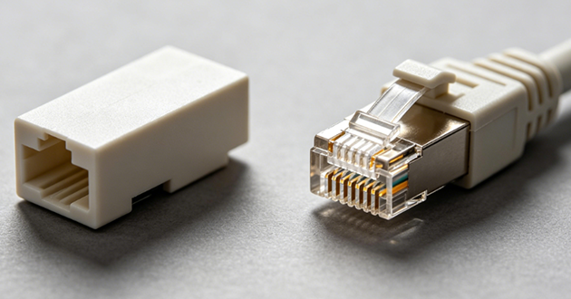
5.What are the two types of RJ45 connectors?
The two main types of RJ45 connectors are unshielded (UTP) and shielded (STP), both designed for 8P8C Ethernet cables. The key difference lies in whether they include protection against electromagnetic interference (EMI).
Unshielded (UTP) Connectors
UTP connectors are the most commonly used type, typically made of plastic without any metal shielding. They are cost-effective, easy to install, and widely used in standard home and office networks where interference levels are low.
Shielded (STP) Connectors
STP connectors include a metal shield around the connector housing, which helps reduce electromagnetic interference. They are usually paired with shielded cables and are ideal for industrial environments or areas with high electrical noise.
Key Difference:
UTP: No shielding, suitable for everyday networking
STP: With shielding, better for high-interference environments