The most common RJ45 pinout is T568B, which is widely used for Ethernet patch cables, commercial networks, routers, switches, gateways, and IP camera connections. However, choosing the right wiring standard is not only about popularity. T568A may still be required for existing cabling systems or specific project standards.
For reliable Ethernet performance, correct wiring is only the first step. In PoE, Gigabit Ethernet, and network equipment design, the RJ45 connector, RJ45 jack, shielding, PCB layout, and magnetic integration also affect long-term connection stability.
Table of Contents
1.Quick Answer: The Most Common RJ45 Pinout Is T568B
2.T568B RJ45 Wiring Order and T568A Comparison
3.When to Use T568B Pinout or T568A
4.Why RJ45 Connector Pinout Matters for PoE and Ethernet Performance
5.RJ45 Connector Selection for Ethernet Device Design
6.Common RJ45 Pinout Mistakes and FAQ
Quick Answer: The Most Common RJ45 Pinout Is T568B
The most common RJ45 pinout is T568B. It is widely used for Ethernet patch cables, commercial networks, routers, switches, gateways, access points, IP cameras, and many other network connections.
For most new Ethernet patch cables, T568B is the practical default. It is familiar to installers, easy to identify, and commonly used in many commercial network environments.
However, “most common” does not mean “always correct.” If an existing cabling system uses T568A, or if a project specification requires T568A, the right choice is to match that standard.
The key rule is simple: for a normal straight-through Ethernet cable, both ends should use the same wiring standard. T568B is not faster than T568A, and T568A is not less reliable. The difference is wiring arrangement, not Ethernet performance.
For device manufacturers, pinout is only part of the Ethernet connection. The RJ45 connector, PCB footprint, shielding structure, and magnetic design also affect the final performance of the device.

T568B RJ45 Wiring Order and T568A Comparison
The T568B RJ45 wiring order defines how the eight wires inside an Ethernet cable are arranged from pin 1 to pin 8. When users search for the most common RJ45 pinout, this color order is usually the most important information they need first.
Pin Number | T568B Wire Color | Pair |
Pin 1 | White / Orange | Pair 2 |
Pin 2 | Orange | Pair 2 |
Pin 3 | White / Green | Pair 3 |
Pin 4 | Blue | Pair 1 |
Pin 5 | White / Blue | Pair 1 |
Pin 6 | Green | Pair 3 |
Pin 7 | White / Brown | Pair 4 |
Pin 8 | Brown | Pair 4 |
1.T568A vs T568B Ethernet Cable Wiring
T568A and T568B are the two main Ethernet cable wiring standards used with RJ45 connectors. Their main difference is the position of the orange and green wire pairs. In T568B, the orange pair is placed on pins 1 and 2, while the green pair is placed on pins 3 and 6. In T568A, these two pairs are reversed.
Both standards can support Ethernet performance when correctly terminated with the right cable and connector. The important point is not which one is faster, but whether the cable is wired consistently.

2.Straight-Through Cable vs Crossover Cable
If both ends use T568B, the cable is a straight-through cable. If both ends use T568A, it is also a straight-through cable.
If one end uses T568A and the other end uses T568B, the cable becomes a crossover cable. Modern devices often support auto-MDI/MDIX, but for standard Ethernet cabling, it is still better to avoid mixing standards unless a crossover cable is intentionally required.
For most standard Ethernet connections, use the same wiring standard on both ends.
When to Use T568B Pinout or T568A
The T568B pinout is usually the right choice for new Ethernet patch cables when there is no special requirement for T568A.
1.Use T568B for New Ethernet Patch Cables
T568B is widely used and easy for technicians to identify, test, and maintain. It is suitable for common network connections in offices, equipment rooms, industrial cabinets, security systems, and field installations.
For new patch cables, commercial network projects, router connections, switch cabinets, and general Ethernet wiring, T568B is often the most practical choice.

2.Use T568A When the System Requires It
Although T568B is the most common RJ45 pinout, T568A is still valid. If a building, cabinet, or structured cabling system already uses T568A, new cables should continue with T568A.
Some residential wiring systems, public projects, or legacy installations may also specify T568A. In these cases, the project requirement should come first.
The best standard is not always the most popular one. It is the one that matches the actual cabling system and keeps future maintenance simple.
Why RJ45 Connector Pinout Matters for PoE and Ethernet Performance
RJ45 connector pinout matters, but correct wiring alone is not enough for PoE, Gigabit Ethernet, 2.5G, 5G, or 10G Ethernet.
For Gigabit Ethernet and higher-speed connections, all four twisted pairs are used for data transmission. Wrong wiring, split pairs, or poor termination may cause connection failure, unstable transmission, or speed downgrade.
1.Correct Pinout Helps Maintain Signal Quality
A correct RJ45 connector pinout helps maintain pair balance and signal integrity. This is especially important for high-speed Ethernet, where small wiring or termination problems can affect data transmission.
For Cat5e, Cat6, Cat6A, and higher-performance cables, the cable category, conductor size, plug design, and device-side connector should match the actual application.

2.PoE Requires Connector Reliability
PoE sends power and data through the same Ethernet connection. Even with correct T568B wiring, poor connector contact may cause power loss, heating, or unstable operation.
For PoE devices, engineers should not only check the wiring order. They should also consider contact resistance, terminal quality, connector material, shielding structure, PCB grounding, and long-term current stability.
This is why choosing a suitable PoE RJ45 connector is as important as following the correct wiring order.
RJ45 Connector Selection for Ethernet Device Design
For cable assembly, users often focus on wire color. For equipment design, the RJ45 connector itself is a key part of the Ethernet interface.
The RJ45 pinout defines the cable plug wiring. The device-side RJ45 jack must also match the PCB layout, enclosure opening, grounding method, port direction, and production process.
This matters for network switches, routers, gateways, industrial controllers, security equipment, and OEM Ethernet devices.
1.Key Factors in PCB Mount RJ45 Jack Selection
When selecting a PCB mount RJ45 jack, engineers should review more than the external port shape.
Selection Factor | Engineering Consideration |
Mounting type | Through-hole, SMT, or mixed mounting |
Port orientation | Right angle, vertical, opening up, or opening down |
Shielding | Shielded or unshielded structure |
LED option | With or without integrated LED |
EMI tabs | Grounding and interference control |
Port count | Single-port or multi-port design |
PCB footprint | Board layout compatibility |
Panel fit | Enclosure and front-panel matching |
A connector may follow the correct pinout but still fail to match the PCB or housing. That can delay development, increase redesign cost, or affect production stability.

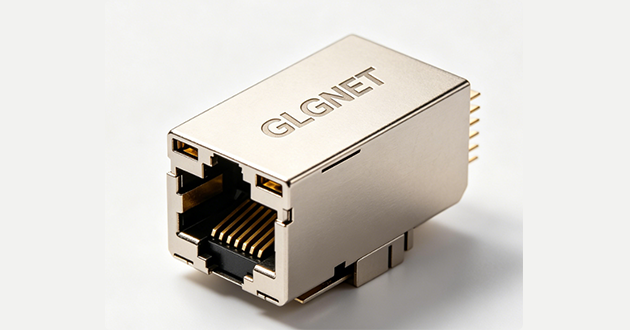
2.Magnetic RJ45 Connector for Network Equipment
A Magnetic RJ45 connector integrates Ethernet magnetics into the RJ45 interface. It can help simplify PCB design and support compact Ethernet equipment layouts.
For OEM projects, engineers should check Ethernet speed, PoE support, LED configuration, shielding, PCB footprint, EMI performance, and sample availability.
GLGNET provides Ethernet connector solutions for network equipment, industrial devices, communication systems, and OEM projects. The focus is not only supplying a standard part, but helping customers match the connector to the actual device design.
The right RJ45 connector should support correct wiring, stable electrical performance, and long-term device reliability.

Common RJ45 Pinout Mistakes and FAQ
1.Common RJ45 Pinout Mistakes to Avoid
One common mistake is mixing T568A and T568B by accident. This creates an unintended crossover cable and may cause confusion during testing or maintenance.
Another issue is split pair wiring. A cable may look correct by color order, but if the twisted pairs are not arranged correctly, signal performance can suffer. This is especially important for Gigabit Ethernet and higher-speed networks.
Using the wrong connector for the cable can also cause problems. Cat6 and Cat6A cables may have larger conductors or thicker insulation, so the plug or jack should match the cable structure.
Shielding is another detail that should not be ignored. Shielded cables should be used with suitable shielded connectors and proper grounding design. Otherwise, the shielding benefit may be reduced.
For PoE applications, correct wiring does not automatically guarantee stable power delivery. The connector also needs reliable contact design and suitable electrical performance.
2.What is the most common RJ45 pinout?
The most common RJ45 pinout is T568B. It is widely used for modern Ethernet patch cables and many commercial network installations.
3.Is T568A or T568B better?
Neither is better in performance. T568B is more common, while T568A may be required by existing cabling or project standards.
4.Can I mix T568A and T568B?
Yes, but it creates a crossover cable. For a normal straight-through Ethernet cable, both ends should use the same standard.
5.Does T568B support PoE?
Yes. T568B can support PoE when the cable, connector, and device design meet the required specifications.
6.Is the RJ45 pinout the same for Cat5e, Cat6, and Cat6A?
T568A and T568B can be used with Cat5e, Cat6, and Cat6A cables. The connector should match the cable diameter, wire gauge, shielding type, and performance requirement.
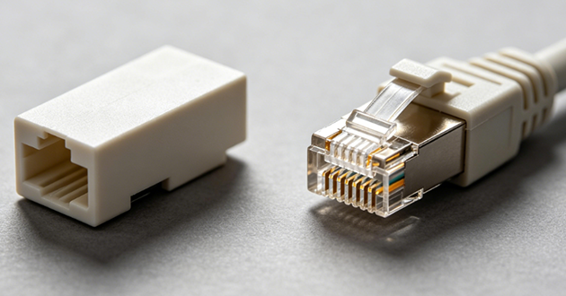
7.Is an RJ45 jack the same as an RJ45 plug?
No. An RJ45 plug is attached to the cable end, while an RJ45 jack is usually mounted on a device, PCB, wall plate, or panel.
Conclusion
T568B is the most common RJ45 pinout for modern Ethernet cables, especially in commercial networks and new patch cable applications. T568A is still correct when required by an existing system or project standard.
For reliable Ethernet, the wiring order is only the first step. PoE, Gigabit Ethernet, shielding, PCB layout, and connector structure all affect final connection quality.
For equipment manufacturers, selecting the right RJ45 connector, RJ45 jack, or Magnetic RJ45 connector helps improve design compatibility, reduce testing risk, and support stable Ethernet performance. GLGNET supports customers with practical RJ45 connector selection for Ethernet device projects.