This guide demystifies the sfp connector and qsfp connector families so you can choose the right port and module with confidence. We’ll start with a quick SFP vs QSFP comparison, define each form factor, highlight the practical differences (lanes, density, cabling, use cases, thermals, compatibility), and finish with a step-by-step checklist for selecting SFP transceivers that match your speed, reach, and plant.
Quick comparison: SFP vs QSFP
Item | SFP | QSFP |
Electrical lanes | 1 lane | 4 lanes (QSFP-DD = 8 lanes) |
Common speeds | 1G (SFP), 10G (SFP+), 25G (SFP28), 50G (SFP56, PAM4) | 40G (QSFP+), 100G (QSFP28), 200G (QSFP56, PAM4), 400/800G (QSFP-DD) |
Front connectors | LC (optics), RJ-45 (copper), fixed DAC/AOC | MPO/MTP (parallel), some LC (e.g., LR4/CWDM4), fixed DAC/AOC |
Typical roles | Access/edge uplinks, server NICs, ToR short runs | Aggregation/spine/backbone, high-bandwidth uplinks |
Breakout support | N/A (single lane) | Yes (e.g., 100G → 4×25G, 40G → 4×10G) — device-dependent |
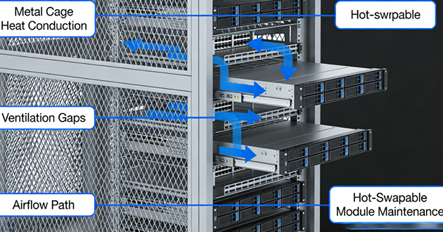
Power/thermals | Lower (varies by module; RJ-45 higher) | Higher at top speeds; plan airflow |
Compatibility notes | Many SFP+ ports run 1G SFP; some SFP28 can downshift to 10G | Breakout/speed-step features depend on platform/firmware |
What is an SFP Connector?
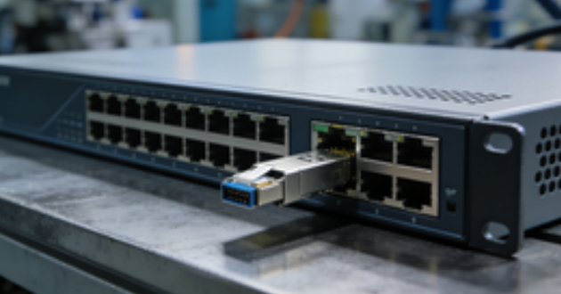
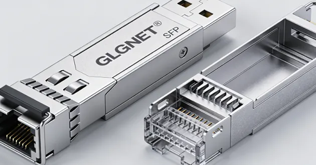
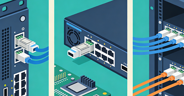
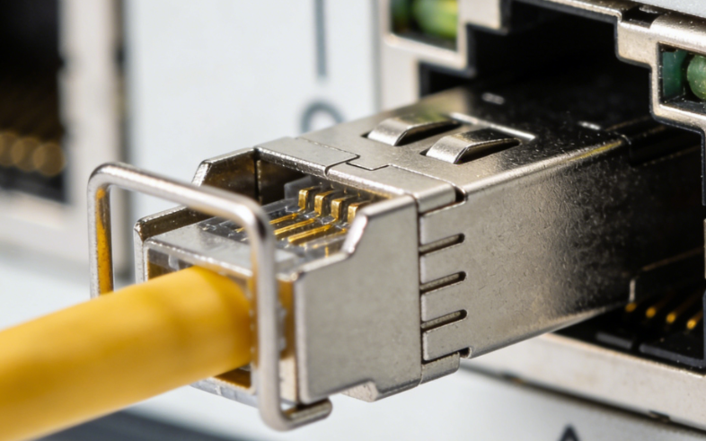
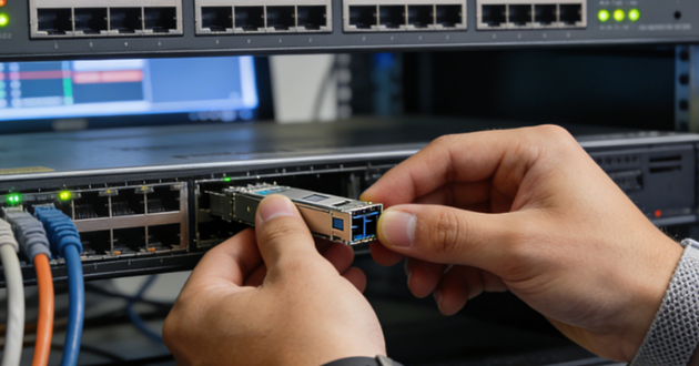
An SFP (Small Form-factor Pluggable) is a hot-swappable, single-lane transceiver: the switch/router/NIC provides the internal electrical interface, while the sfp connector on the bezel presents the external physical interface—typically LC for optics or RJ-45 for copper. The SFP family spans SFP (1G), SFP+ (10G), SFP28 (25G), and SFP56 (50G, PAM4), with specialized variants such as BiDi (single-fiber), CWDM/DWDM (wavelength-specific), and pre-terminated DAC/AOC for short, tidy runs.
Electrically, SFPs align with host line codes (e.g., 1000BASE-X, 10GBASE-R, 25GBASE-R) and expose DOM/DDM over I²C (temperature, voltage, Tx/Rx power) so you can monitor link health and power budget. RJ-45 SFP connector modules embed a full BASE-T PHY with DSP for echo/NEXT cancellation—great for reusing Cat5e/6/6A—at the cost of higher power and a touch more latency than optics or DAC. In practice, SFPs dominate the access and server edge: 1G for management/legacy, 10G SFP+ for ToR uplinks and low-latency hosts, 25G SFP28 for leaf–spine, and 50G SFP56 where single-lane PAM4 is supported. Many SFP+ cages accept 1G SFPs, and some SFP28 ports can run 10G—always per platform capabilities.
What is a QSFP Connector?
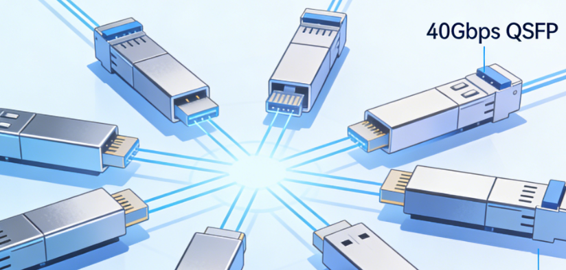
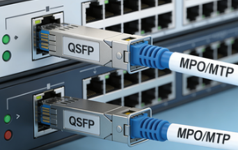
QSFP (Quad Small Form-factor Pluggable) extends the SFP idea to four electrical lanes in one module (and eight in QSFP-DD). Each generation scales total bandwidth by lane speed: QSFP+ 40G (4×10G NRZ), QSFP28 100G (4×25G NRZ), QSFP56 200G (4×50G PAM4), and QSFP-DD 400/800G (8×50/100G). On the front, a qsfp connector typically uses MPO/MTP for parallel fiber, while some long-reach 100G options (e.g., LR4/CWDM4) expose duplex LC by multiplexing wavelengths inside the module.
A signature advantage of the qsfp connector is breakout: one QSFP port can fan out to multiple lower-speed links (for example, 100G → 4×25G SFP28, 40G → 4×10G SFP+) when the platform and cables support it—ideal for aggregation and spine layers that need high throughput with flexible downstream connectivity. At higher rates, expect PAM4 signaling, often mandatory FEC, and a larger power/thermal envelope, so plan airflow and spacing carefully in dense faceplates.
What is the difference between SFP and QSFP?
Lanes & throughput
An sfp connector carries a single electrical lane, while a qsfp connector aggregates four lanes in one module (eight in QSFP-DD). More lanes mean higher aggregate bandwidth and the option to fan out a fast port into several slower ones (e.g., 100G → 4×25G). Per-lane signaling evolves with generations: earlier parts use NRZ, newer 50G/200G+ families use PAM4, which typically pairs with FEC to meet BER targets. In practice, plan topology around lane count × lane rate, not just the headline speed.
Port density
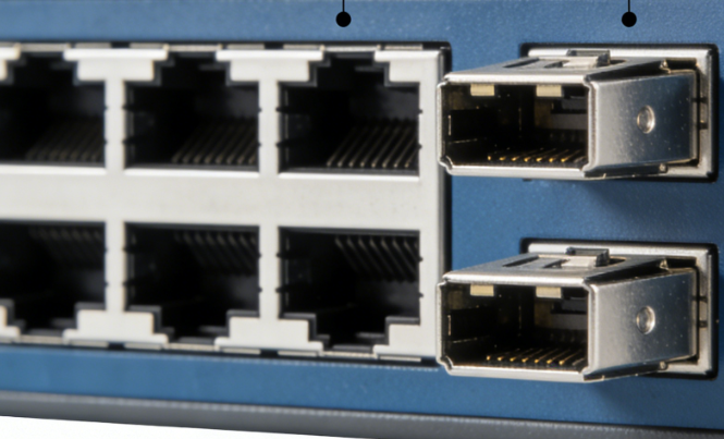
On the same faceplate, QSFP delivers more total throughput per rack unit, whereas SFP maximizes port count for edge/access fan-out. Many fixed switches mix both: rows of sfp connector cages for 1/10/25G endpoints, plus qsfp connector rows for 40/100/200G uplinks. Think QSFP for bandwidth consolidation, SFP for many endpoints, balancing panel space, switch silicon, and cabling complexity.
Cabling & connectors
SFP optics typically present LC duplex (or RJ-45 for copper), keeping patching simple and fiber counts low. A qsfp connector commonly uses MPO/MTP for parallel optics; some long-reach 100G options (e.g., LR4/CWDM4) still expose LC by multiplexing wavelengths inside the module. With MPO/MTP, mind polarity, pinned/unpinned ends, and trunk quality; for breakouts, use MTP→4×LC harnesses. Across both families, clean endfaces matter—contamination is a classic cause of intermittent flaps.
Use cases
SFP dominates access and server NICs: 1G for management, 10G SFP+ for ToR/server links, 25G SFP28 for modern leaf–spine, and 50G SFP56 where single-lane PAM4 is available. QSFP owns aggregation, spine, and backbone at 40/100/200/400G+, and can break out to SFP speeds to feed many lower-rate ports from a single high-rate uplink. This split keeps fabrics scalable and lets you right-size optics per hop.
Power & thermals
Higher-rate QSFP modules draw more power and need stronger airflow (QSFP28 often ~3.5–5 W; QSFP-DD higher). Dense SFP banks still need care: RJ-45 SFPs are notably warm (~2–3+ W), and some SFP28 optics approach ~2 W. Leave breathing room, avoid tight cable bundles over vents, and watch DOM temperatures to catch hot spots before they cause throttling or flaps.
Compatibility
Many SFP+ ports accept 1G SFPs; some SFP28 ports can operate at 10G with the right optics/cables—but behavior is platform-specific. QSFP features like breakout and speed profiles are firmware-controlled; always consult the device’s optics matrix. Physical cross-fit isn’t 1:1—QSFP cages don’t accept SFP modules directly (there are QSA adapters, but they’re vendor-specific). Also factor in EEPROM coding/whitelists and FEC policy at higher speeds to avoid link-up surprises.
How to Choose SFP Connectors Transceivers?
Target speed & host capability
Match the port’s rate/encoding (1/10/25/50G; NRZ or PAM4) and any FEC requirement. Many 25G links assume RS-FEC to meet BER targets. Check if the slot supports downshift (e.g., 10G on an SFP28 port) and whether newer cages accept older modules. Fiber links are generally fixed-rate, so both ends must agree on speed and FEC. If you’re mixing SFP connector and QSFP uplinks, confirm the host profile and breakout rules before choosing the sfp connector type.
Medium & reach
Select optics by distance and fiber: SR on OM3/OM4 for short runs; LR/ER/ZR on OS2 for long spans; BiDi for single-strand links; CWDM/DWDM when you need wavelength multiplexing. For very short, clean paths, use DAC (≈1–5 m) or AOC (≈3–30 m). Reusing copper? Choose an RJ-45 SFP (≤100 m; 10GBASE-T typically needs Cat6A). Always validate the link budget—reach depends on TX power, path loss, and RX sensitivity.
Connector & plant
Ensure the module’s front end—LC, RJ-45, or MPO/MTP—matches your patch field and polarity. Keep LC ferrules clean; many intermittent flaps are contamination, not optics. Do a quick budget check (TX power − total loss ≥ RX sensitivity) and remember extra panels/splices consume margin. Document which sfp connector types sit at each panel to avoid turn-up mismatches.
Device interoperability
Verify vendor coding/whitelists, available DOM/DDM telemetry, and any downshift behavior your ports support. When mixing brands, align EEPROM profiles and alarm thresholds to prevent nuisance warnings. Confirm software as well—some platforms enable FEC or special modes only on specific releases, and certain sfp cages enforce stricter checks.
Power, thermals, environment
Check module wattage and chassis airflow—dense faceplates and RJ-45 SFPs run warm. Align airflow direction across gear, avoid tight cable bundles over vents, and leave breathing room where possible. For harsh sites, pick industrial/extended-temp optics and consider coated PCBs, locking latches, and sealed sfp connector / sfp cage options.
Operations & spares
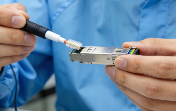
Standardize a compact kit—SR, LR, DAC, RJ-45—and label modules clearly. Monitor DOM/DDM (temperature, Tx/Rx power, laser bias) and alert on trends, not just hard thresholds. Keep dust caps and a cleaning kit with your spares; in practice, more links are fixed with swabs and alcohol than with new optics.
With these checks, you’ll know when SFP suits flexible edge/access links and when a QSFP uplink is the better fit—while selecting SFP transceivers and the right sfp connector for your distance, cabling plant, thermal envelope, and platform compatibility.
Conclusion
When you decide between SFP and QSFP, think in lanes and roles: use sfp connector ports for flexible edge/access fan-out and qsfp connector ports for high-bandwidth aggregation—with breakout where your platform allows. Before ordering, align speed/encoding and FEC at both ends, verify compatibility (coding/whitelists, breakout rules), validate link budget, and account for power/thermals.
FAQs
1.Is SFP+ faster than RJ45?
Yes—SFP+ is generally faster and more efficient than RJ45, especially for 10Gbps and higher-speed networking. While both can support 10Gbps, SFP+ delivers lower latency, reduced power consumption, and better scalability for future high-speed upgrades.
How they compare:
Performance & Speed
SFP+ is optimized for high-speed data transmission and can easily scale beyond 10Gbps (such as 25G or higher), while RJ45 (10GBASE-T) is more complex and less efficient at those speeds.
Latency
SFP+ connections typically have lower and more stable latency, whereas RJ45 introduces additional delay due to signal processing.
Power Consumption
SFP+ uses less power per port, while RJ45 ports generally consume more energy and generate more heat, especially at 10Gbps.
Distance & Flexibility
SFP+ supports both fiber (long-distance, even kilometers) and DAC cables (short-distance), offering more flexibility. RJ45 is usually limited to copper cables with a maximum distance of about 100 meters.
Cost
RJ45 is more cost-effective and widely used, while SFP+ requires additional modules, making it more expensive.
When to choose each:
SFP+: Ideal for data centers, high-performance networks, and long-distance or high-speed connections
RJ45: Better for everyday networking, short-distance connections, and PoE-powered devices
2.Can I use sfp+ transceiver in QSFP28 ports?
No, you cannot plug an SFP+ transceiver directly into a QSFP28 port because the two modules have different physical sizes and interface designs. However, you can still use an SFP+ module in a QSFP28 port by using compatible adapters or breakout solutions.
How it can be done:
Using a QSA Adapter
A QSFP-to-SFP (QSA) adapter allows you to insert an SFP+ module into a QSFP28 port, enabling the port to operate at lower speeds such as 10Gbps.
Using Breakout Cables
QSFP28 ports can also be split into multiple lower-speed connections (e.g., 4×10G) using breakout DAC or AOC cables, depending on switch support.
Things to consider:
Physical difference: SFP+ is a single-lane 10G interface, while QSFP28 is a 4-lane 100G interface
Port configuration: The switch port must support breakout or adapter mode
Speed compatibility: Using adapters reduces the port to lower speeds (e.g., 10G)
Alternative option: SFP28 (25G) modules are often a better match for higher-speed environments
3.Will a 10Gb SFP+ work in a 1Gb port?
In most cases, no—a 10Gb SFP+ module will not work in a 1Gb SFP port. Although they share the same physical form factor, 1Gb ports typically cannot support the higher data rate or signal requirements of 10Gb modules.
Why it usually doesn’t work:
A 1Gb SFP port is designed for lower-speed operation and often lacks the capability to recognize or downshift a 10Gb SFP+ module. As a result, the link will not establish even though the module physically fits.
Possible exceptions:
In rare cases, certain network devices may support dual-rate operation or allow manual speed configuration. Some DAC cables or specialized transceivers might function if explicitly supported by the hardware—but this is not common and should not be relied on.
Best practice:
Use 1G SFP modules for 1Gb ports
Use 10G SFP+ modules for 10Gb ports
Note that SFP+ ports are often backward compatible with 1G SFP modules, but not the other way around
4.What is the difference between SFP 28 and QSFP 28?
The main difference between SFP28 and QSFP28 is speed and channel count: SFP28 is a single-lane 25Gbps transceiver, while QSFP28 is a four-lane 100Gbps (4×25G) module designed for higher-capacity networking.
How they differ in practice:
Speed & Architecture
SFP28 handles one 25G channel, making it suitable for individual device connections. QSFP28 combines four 25G lanes into a single 100G link for much higher throughput.
Form Factor
SFP28 modules are compact (similar to SFP+), allowing high port density for 25G connections. QSFP28 modules are larger to support multiple channels in one interface.
Typical Use Cases
SFP28 is commonly used for switch-to-server or access-layer connections. QSFP28 is mainly used for switch-to-switch links in data centers, especially in aggregation or core layers.
Breakout Flexibility
QSFP28 ports can be split into multiple lower-speed links, such as 4×25G SFP28, using breakout cables—something SFP28 cannot do.
Cost Efficiency
SFP28 is cheaper per module, but QSFP28 is more efficient when you need higher total bandwidth (100G).
5.Why is SFP+ so expensive?
SFP+ modules are more expensive than standard 1G SFP modules because they are designed to handle high-speed 10Gbps data transmission, requiring advanced components and precise manufacturing. Their higher cost reflects the combination of sophisticated technology, low production volumes, and brand premiums.
Reasons for the high cost:
Advanced Technology
SFP+ modules must maintain signal integrity at 10Gbps, support long-distance links, and deliver low-latency performance, which demands superior optical and electronic components compared to 1G modules.
Lower Production Scale
Although widely used, 10G components are still produced in smaller quantities than older 1G SFPs, keeping manufacturing costs higher per unit.
Brand Premiums
Major vendors like Cisco or Juniper often charge extra for branded optics to cover R&D, certification, and profit margins. Third-party compatible modules can be significantly cheaper.
High Performance Requirements
Data center networks require extremely reliable, low-latency, and high-bandwidth operation, which adds complexity and cost to the manufacturing process.