This article is about making that concrete: how per-lane signaling and modulation map each generation; what changes at the qsfp connector/qsfp-dd connector and cage level.
QSFP-DD: Aggregate data rate
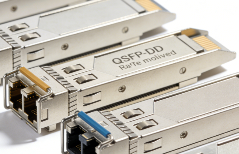
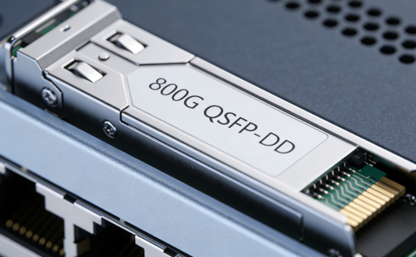
QSFP-DD (Quad Small Form-factor Pluggable — Double Density) uses eight electrical lanes, allowing the form factor to scale from 200/400G to 800G as per-lane signaling increases. In deployed systems, 400G QSFP-DD aggregates 8×50G PAM4, while 800G QSFP-DD800 reaches 8×100G PAM4 (electrical lanes commonly ~53.125/106.25 Gb/s). The double-row contact design that carries the extra lanes is often mechanically backward-compatible: many QSFP-DD cages accept legacy QSFP family modules (e.g., QSFP28 100G) and run them at the module’s native rate, which preserves panel density and simplifies staged migrations.
A wide optic ecosystem supports different plants and distances—SR8 for short multimode runs, plus DR8/FR8/LR8 families for single-mode spans—delivered via parallel lanes or internal WDM, depending on the optic. Higher aggregate speeds raise the power and thermal envelope, so platforms pairing QSFP-DD typically emphasize clear airflow paths, adequate heat sinking, and slot-level power budgeting. On the control plane, CMIS management extends the I²C map with richer telemetry (temperature, power, alarms, fault states), helping operators monitor module health and maintain stability on dense 400/800G faceplates.
QSFP-DD Cage Generation Map: Per-Lane Rate, Modulation, And Totals
QSFP-DD cage headline speeds follow a simple rule: lane rate × lane count. Early implementations used 8×25G NRZ for 200G; mainstream builds pair 8×50G PAM4 (≈53.125 Gb/s electrical lanes) to hit 400G; and current high-end modules run 8×100G PAM4 (≈106.25 Gb/s per lane) for 800G. Because PAM4 carries two bits per symbol, it doubles per-lane throughput versus NRZ but squeezes the signal-to-noise margin—so FEC (e.g., KP4/RS-FEC) is effectively mandatory to achieve target BER on real links.
Design implications. On the host side, a QSFP-DD path benefits from low-jitter reference clocks, the right mix of TX pre/de-emphasis and RX equalization (CTLE/DFE), and retimers where board or connector loss eats margin. On the optical side, lane speed steers topology: keep it parallel (e.g., SR8/DR8 with MPO/MTP on the qsfp connector) or use internal WDM to present LC while sustaining higher per-lane rates. Decide the per-lane rate you can reliably support—electrically and optically—and then match the QSFP-DD generation and optic (reach class, connector style) to your plant so turn-ups are predictable and painless.
What is the difference between QSFP Connector and QSFP-DD Connector?
QSFP vs QSFP-DD — quick comparison
|
Item |
qsfp connector |
qsfp-dd connector |
|
Electrical lanes |
4 lanes |
8 lanes |
|
Typical aggregates |
40/100/200/400G (4×10/25/50/100G) |
400/800G (8×50/100G) |
|
Per-lane signaling |
NRZ (10/25G), PAM4 (50/100G) |
PAM4 (50/100G) |
|
Front connectors |
MPO/MTP (parallel) or LC (e.g., FR4/LR4) |
MPO/MTP (parallel) or LC (some WDM parts) |
|
Breakout |
Yes (e.g., 100G→4×25G, 40G→4×10G) |
Yes (e.g., 400G→4×100G) — platform-dependent |
|
Mechanical |
Standard QSFP depth |
Slightly deeper, dual-row contacts |
|
Backward fit |
- |
Many cages accept legacy QSFP modules at native speed |
|
Power / cooling |
Lower to moderate (up to ~400G) |
Higher (400/800G): tighter airflow and heatsinking |
|
Typical roles |
Access/aggregation uplinks, spine at ≤400G |
High-density 400/800G spine/aggregation in same faceplate area |
Lanes & bandwidth
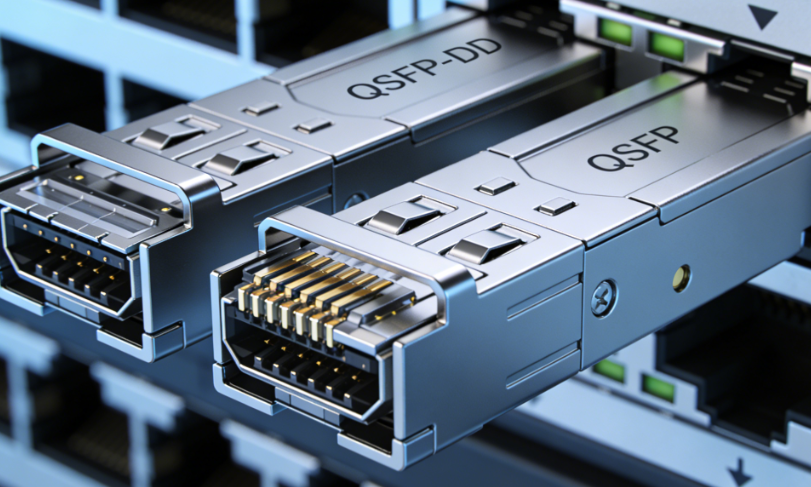
The clearest separator is lane count. A qsfp connector carries 4 lanes, so totals scale with per-lane speed—4×10/25G NRZ → 40/100G, then 4×50/100G PAM4 → 200/400G. A qsfp-dd connector doubles that to 8 lanes, reaching 400G (8×50G PAM4) and 800G (8×100G PAM4) in roughly the same panel space. When planning capacity or oversubscription, think lane rate × lane count, not just the headline speed.
Mechanics & compatibility
QSFP-DD adds a second row of contacts and a little extra depth to carry the additional lanes. Even so, many QSFP-DD cages are engineered to accept legacy QSFP modules and run them at the module’s native rate—useful for staged upgrades where only some links move to 400/800G. Still verify vendor coding/whitelists and power budgets before mixing generations.
Cabling & front-end options
Both families ship with MPO/MTP for parallel optics (e.g., DR4/DR8/SR4/SR8). For longer reaches, modules often use internal WDM so the faceplate presents duplex LC (e.g., FR4/LR4). With MPO/MTP, plan polarity (Type A/B/C), pinned vs. unpinned ends, and trunk fiber count (12/16-fiber). With LC, keep endfaces clean and respect bend radius—contamination or tight bends are classic causes of intermittent errors. Choose the front end that matches your plant, then pick the qsfp connector/qsfp-dd connector optic accordingly.
Breakout & topology design
QSFP ports often break out 100G → 4×25G or 40G → 4×10G to feed multiple lower-rate endpoints; QSFP-DD extends this to 400G → 4×100G (platform-dependent). Breakout is powerful at aggregation boundaries—one high-rate port can serve several lower-rate links—provided your switch/NIC profiles support it, the MTP→4×LC (or MTP) harness is correct, and optics/FEC settings match on each child link.
Power & thermals
More lanes and higher signaling rates raise module wattage. Dense banks of 400/800G QSFP-DD need unobstructed airflow, effective heat-sinking, and tidy cable dressing so vents stay clear. QSFP deployments also benefit from good hygiene: monitor DOM temperatures, align airflow (F2B/B2F) across gear, leave a little spacing when possible, and use blanking panels to prevent recirculation—especially when QSFP rows sit near warm modules in adjacent SFP banks.
What Is The Maximum Data Rate for QSFP?
For the classic 4-lane QSFP family, the ceiling is 400G in the QSFP112 generation—electrically 4×100G PAM4 within the familiar form factor. You’ll see optics like DR4 (parallel SMF with MPO/MTP) and FR4 (duplex LC via internal CWDM), letting you choose parallel or wavelength-multiplexed patching without changing the qsfp connector on the chassis; many platforms also offer LR4 for longer reach. If you need more than 400G per port, step up to QSFP-DD, where the qsfp-dd connector doubles lanes to eight and delivers 400/800G in nearly the same faceplate footprint—while many QSFP-DD cages remain backward-friendly to legacy QSFP modules, making staged migrations straightforward.
Conclusion
Treat lane architecture as your compass. Use the qsfp connector where you want flexible fan-out and broad optic choices; step up to the qsfp-dd connector when you need more bandwidth in the same faceplate space while keeping migration options open.