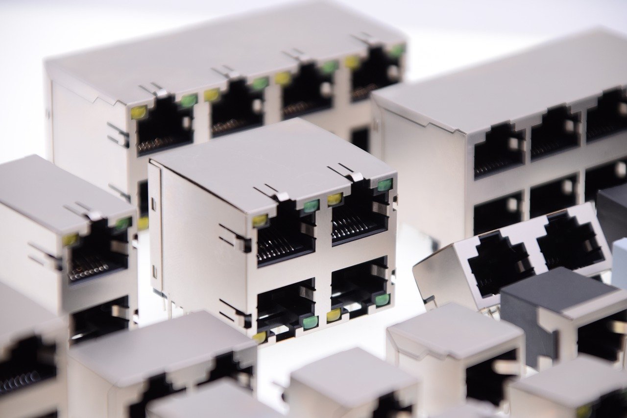
While SFP and SFP+ cages may seem interchangeable at first glance, they differ significantly in electrical characteristics, thermal handling, and system-level integration. This blog dives into the key distinctions between SFP and SFP+ cages, with practical insights into compatibility, PCB layout strategies, and thermal design considerations in high-density environments.
1.SFP vs SFP+ Cage: Core Differences
While SFP and SFP+ cages may appear similar externally, their internal specifications and performance capabilities differ significantly. Understanding these distinctions is essential for system designers, hardware engineers, and IT professionals working with high-speed networking infrastructure.
Here’s a breakdown of the core distinctions between the two:
|
Feature |
SFP Cage |
SFP+ Cage |
|
Data Rate Support |
Up to 1.25 Gbps |
Up to 10 Gbps |
|
Signal Integrity Design |
Basic differential signaling |
Enhanced trace routing, improved EMI shielding |
|
Thermal Handling |
Standard airflow, limited heat dissipation |
Optimized for higher heat loads, often includes vented designs |
|
Material Construction |
Standard stamped metal |
Higher-grade alloys, additional ground spring fingers |
|
Module Compatibility |
Only SFP modules |
Supports both SFP and SFP+ modules (in many cases) |
|
Use Case |
Enterprise switches, legacy routers |
High-performance servers, data center aggregation, storage fabrics |
2.SFP/SFP+ Cages Compatibility and Design Implications
Choosing between SFP and SFP+ cages involves more than matching data rates. Engineers must account for mechanical fit, electrical compatibility, and thermal behavior to ensure stable performance under real-world operating conditions.
2.1Module-to-Cage Interoperability: Physical ≠ Functional
It’s a common misconception in network hardware design: if a transceiver fits into the cage, it should work. While SFP and SFP+ modules share identical mechanical dimensions and sfp/sfp+ connectors interfaces, electrical and logical compatibility is far more nuanced.
Let’s unpack why “physical ≠ functional” when it comes to SFP and SFP+ module-to-cage integration:
Voltage Rail Mismatches
One of the most critical (yet overlooked) issues lies in power supply expectations. Many legacy SFP modules—particularly those designed before the proliferation of SFP+—require a 3.3V logic level for proper operation. In contrast, modern SFP+ ports may regulate certain internal lanes for 2.5V signaling, optimized for high-speed data transmission.
Firmware & Host-Level Restrictions
Modern network switches, routers, and server NICs increasingly rely on firmware-based validation layers to manage transceiver behavior. Even if the module technically fits and powers on, the host device might refuse to initialize it for several reasons:
The module’s EEPROM doesn’t pass digital diagnostics (DDM) checks.
It lacks the proper vendor code (e.g., not from an approved list).
It’s operating outside of certified power or temperature thresholds.
Active vs Passive Signal Expectations
At the board level, signal routing strategies differ between SFP and SFP+. While both use differential signaling, SFP+ often requires active signal conditioning, such as pre-emphasis or equalization—especially over longer traces or backplane routing.

2.2PCB Layout & Electrical Planning for SFP+ Cages
Designing a high-speed PCB that supports SFP+ cages is far more complex than simply aligning sfp cage connectors and copper pads. Compared to standard SFP layouts, SFP+ cage connectors introduces tighter tolerances, faster signal edges, and stricter requirements for signal integrity.
To ensure reliable 10G transmission and EMI compliance, engineers must address the following key areas:
Controlled Impedance Routing for Differential Pairs
SFP+ interfaces typically carry high-speed differential signals—such as 10GBASE-SR/LR or Fibre Channel—operating in the multi-gigahertz range. At these frequencies, any deviation in trace impedance can lead to significant signal reflection, eye diagram distortion, and insertion loss.
Minimal Trace Length & Path Symmetry
Unlike SFP modules, which tolerate modest trace lengths, SFP+cage connectors layouts must minimize trace length from the PHY or SerDes to the cage interface.
Grounding Strategy and Decoupling
At 10G speeds, even millivolts of noise can cause packet errors or link instability. This makes a robust ground return path critical beneath every high-speed signal.
Managing Crosstalk in High-Density Layouts
In compact form factors—especially 1U switches or embedded network cards—it’s common to see multiple SFP+ cages lined up side by side. Without proper isolation, aggressor signals from one port can bleed into its neighbors, creating deterministic jitter and crosstalk-induced errors.
2.3Thermal and Density Trade-offs: Designing for Heat in High-Port Environments
.As equipment becomes more compact and densely populated, thermal management becomes increasingly critical. This is particularly true in environments like top-of-rack switches and edge appliances.
Shrinking Thermal Budget per Port
In a fully populated 1U switch with 48 SFP+ ports, the thermal budget per port can drop below 3 watts.
This leads to challenges in managing:
|
Challenge |
Cause |
Potential Impact |
|
Limited Thermal Budget |
Less than 3W per port in fully populated 1U chassis |
Reduced margin for heat dissipation |
|
Internal Heat Generation |
High-speed SerDes and laser components inside SFP+ modules |
Localized module heating |
|
Radiated Heat from Adjacent Ports |
Closely packed cages with minimal spacing |
Temperature buildup across port rows |
|
Airflow Obstruction |
Dense layout, poor venting, or cable congestion |
Inefficient heat removal |
|
Thermal Stress Effects |
Accumulated heat without mitigation |
- Link instability (especially for long-reach modules) - Laser wavelength drift - Accelerated aging or hardware failure |
Cage-Level Thermal Relief Features
To support these conditions, SFP+ cages must be designed with built-in thermal management in mind. This includes:
Vent cutouts or “thermal louvers” in the cage walls to allow airflow over and around the module surface.
Heat-conductive cage materials or coated finishes that help dissipate heat into the chassis or heat sink surfaces.
Compatibility with airflow ducting within the chassis—especially front-to-back or back-to-side airflow designs common in data center switches.
Maintaining Clean Cooling Paths
Another common issue in high-density designs is blocked or obstructed airflow. Even if the cage itself is thermally optimized, poor mechanical placement can trap heat between modules.
Mitigating Thermal Crosstalk Between Adjacent Ports
In ultra-compact designs, adjacent SFP+ ports may transfer heat to one another, resulting in “thermal crosstalk.” This can cause localized hotspots even if the total system airflow is sufficient.

In short, thermal design around SFP+ cages isn’t just about cooling the module—it’s about building a thermally aware system that balances performance, density, and longevity. Smart cage selection is a critical piece of that puzzle.
Learn more:
https://www.glgnet.biz/sfp-cage-compatibility-escape-vendor-lock-In-save-costs
Conclusion:
As modern networks continue to push the limits of bandwidth and density, understanding the subtle yet significant differences between SFP and SFP+ cages becomes essential. From electrical compatibility to thermal resilience, each factor can impact overall system reliability and performance.