
Setting up an RJ45 pinout is an essential skill for anyone working with networking, whether you're a professional IT technician or a hobbyist. An RJ45 pinout describes the configuration of wires inside an Ethernet cable, and getting it right is crucial for proper network communication. This guide will walk you through everything you need to know about setting up an RJ45 pinout, including the types of pinouts, the materials you'll need, and step-by-step instructions. By the end of this article, you should feel confident in creating your own RJ45 cable connections.
The RJ45 connector is an 8-pin plug used in Ethernet networking to connect devices like computers, routers, and switches. The pinout refers to how the eight individual wires inside a twisted-pair Ethernet cable are arranged within the RJ45 connector. There are two widely used wiring standards for an RJ45 pinout: T568A and T568B. Both standards serve the same purpose, but they arrange the wires differently to suit different networking needs.
If you want to learn more about what an RJ45 connector is and how to choose the right one for Cat6, click this article to get the details you’re looking for:
https://www.glgnet.biz/articledetail/what-is-an-rj45-connector.html
RJ45 pinouts are important because they determine how the electrical signals are transmitted over the Ethernet cable. Using the correct wiring standard ensures compatibility and reliable data transmission. Miswiring can lead to poor network performance or complete connection failures, so understanding pinouts is crucial for successful Ethernet wiring.
Beyond simply “making it work,” correct RJ45 pinouts help protect signal quality—especially at Gigabit speeds and above—because Ethernet relies on the right conductors staying paired to control noise and limit crosstalk. In practical terms, that means picking one standard (usually T568A or T568B) and using it consistently on both ends, so each twisted pair ends up on the pins it’s meant to serve.
Also, don’t rely on the link light as proof everything is fine. A cable can still show “connected” with a swapped or split pair, but the RJ45 connection may behave poorly in real use—random dropouts, lower throughput, more errors, or PoE devices that act up when power demand increases. The safest approach is careful termination: keep the twists as close to the connector as possible, untwist only what you need, and test the RJ45 cable after crimping to catch problems early—before they turn into hard-to-reproduce network issues.
To set up an RJ45 pinout, you'll need some basic tools and materials:
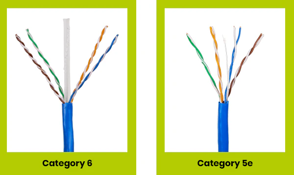
Cat5e or Cat6 Ethernet Cable: Depending on your networking speed requirements.
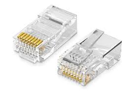
RJ45 Connectors: The plastic plugs that house the wires.
Crimping Tool: To attach the RJ45 connector to the cable.

Wire Stripper: To expose the wires inside the Ethernet cable.

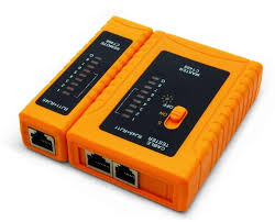
Cable Tester (Optional but recommended): To check the connectivity of your finished cable.
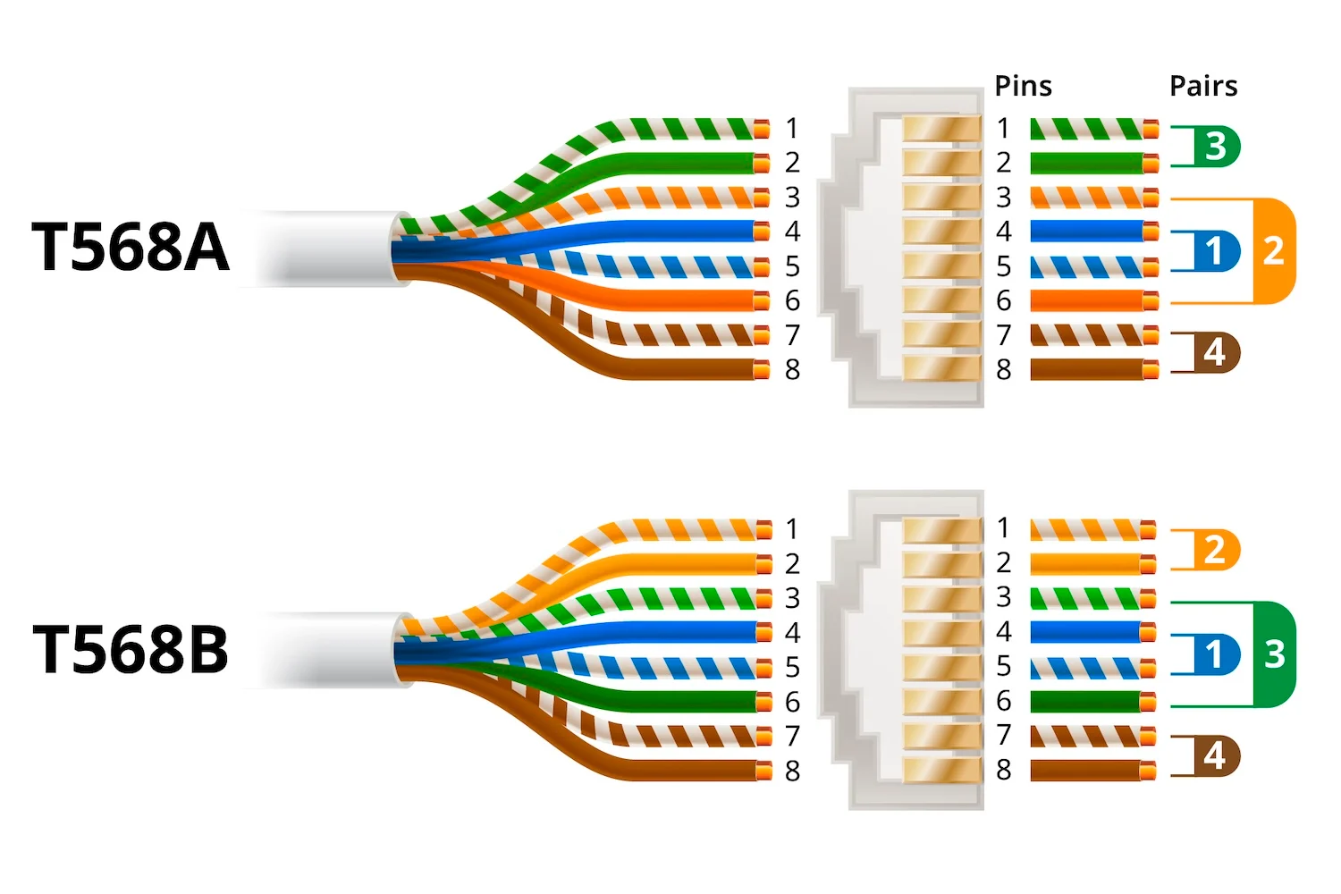
The T568A and T568B standards are the two main wiring schemes for RJ45 pinouts. These standards define how the colors of the eight wires should be arranged within the connector.
T568A: Commonly used in residential applications.
T568B: Often used in commercial settings and is the most widely implemented pinout.
The key difference between T568A and T568B is the arrangement of the green and orange wire pairs. Both configurations support networking, but consistency across your installation is key.
So it’s usually best to follow whatever your existing jacks, patch panels, or pre-terminated cables already use. Mixing standards between ends creates a crossover cable, which most modern networks don’t need and can make future troubleshooting less straightforward.
Begin by stripping about 1 inch (2.5 cm) of the outer jacket from the Ethernet cable using a wire stripper. Be careful not to damage the individual wires inside. After the jacket is off, remove any rip cord or filler, and if your Cat6 cable has a plastic spline/separator, trim it back so the RJ45 connector can seat properly. Keep the pair twists as intact as you can and only untwist what’s necessary to arrange the wires—this helps maintain signal quality. Finally, make sure you’ve stripped the right amount: the cable jacket should extend into the RJ45 connector so the strain relief grips it, instead of putting stress on the individual conductors.
Inside the Ethernet cable, you'll find four twisted pairs of wires. Untwist each pair just enough to work with, then straighten the conductors so they sit flat and aligned. Arrange the wires in the correct order for either the T568A or T568B standard—whichever you’re using for the whole run—and keep that standard consistent on both ends. Use the pinout table below to confirm the color sequence before moving on.
Once the wires are arranged correctly, trim them so they are all the same length—about half an inch (1.3 cm) from the end of the cable jacket. Aim for a clean, straight cut so the conductors slide into the RJ45 connector evenly and reach the front at the same time. If the wires are uneven or too long, they may fold or fail to seat fully; if they’re too short, the connector may not grip the jacket properly for strain relief.
Carefully insert the wires into the RJ45 connector, making sure each wire goes into the correct channel. The connector should have the clip facing down, and each conductor should slide all the way to the front. Take a moment to look through the clear plug and confirm the color order still matches your chosen RJ45 pinout and that the cable jacket has entered the connector far enough to be captured by the strain relief.
Place the RJ45 connector into the crimping tool and squeeze firmly to lock the wires in place. The crimping action drives the metal contacts into the conductors, creating the electrical connection. Make sure you fully close the crimper so the pins set evenly, and confirm the strain relief is gripping the cable jacket (not just the inner wires). When it’s done right, the connector should feel tight and stable, with no loose conductors and no wiggle between the plug and the cable.
If you have a cable tester, use it to verify continuity and confirm the RJ45 pinout is correct from end to end. This quick check helps catch common issues—like a swapped pair, an open wire, or a weak crimp—before the cable goes into service and becomes harder to troubleshoot.
The following table shows the specific pin configuration for both T568A and T568B standards. Each pin number corresponds to a specific color-coded wire in the Ethernet cable. Properly arranging the wires is essential for ensuring compatibility and preventing issues like crosstalk and interference.
|
Pin Number |
T568A Color Code |
T568B Color Code |
|
1 |
Green/White |
Orange/White |
|
2 |
Green |
Orange |
|
3 |
Orange/White |
Green/White |
|
4 |
Blue |
Blue |
|
5 |
Blue/White |
Blue/White |
|
6 |
Orange |
Green |
|
7 |
Brown/White |
Brown/White |
|
8 |
Brown |
Brown |
Pin 1 and Pin 2: These are responsible for transmitting data. In T568A, they are colored Green/White and Green, while in T568B, they are Orange/White and Orange.
Pin 3 and Pin 6: These pins handle the receiving of data. In T568A, they are Orange/White and Orange, whereas in T568B, they are Green/White and Green.
Pin 4 and Pin 5: These pins are used for additional functionalities in some Ethernet systems, such as Power over Ethernet (PoE). Both standards use Blue and Blue/White for these pins.
Pin 7 and Pin 8: These are usually for grounding purposes and other system enhancements. Both standards use Brown/White and Brown.
The choice between T568A and T568B usually comes down to local habits and what’s already installed—not speed or capability, because both standards carry Ethernet just as well when terminated properly. In many homes, T568A is often the default you’ll see referenced (and it’s commonly tied to structured cabling practices), while T568B shows up frequently in commercial buildings and older corporate networks. In real-world jobs, the “best” option is typically the one that matches the existing ecosystem—especially if you’re plugging into patch panels, keystone jacks, or any pre-terminated runs.
Whichever standard you choose, consistency is what keeps everything predictable. A straight-through Ethernet cable should be wired the same way on both ends (A-to-A or B-to-B). If you wire one end as A and the other as B, you’ve effectively made a crossover cable. Modern devices may still link thanks to auto MDI-X, but it can complicate troubleshooting and isn’t a great habit for structured cabling. A solid approach is to standardize on one scheme, document it, stick with it across all drops, and verify each termination with a tester—especially when you’re doing multiple runs or powering devices over PoE, where correct pairing and reliable contact really matter.
Incorrect Wire Order (RJ45 Pinout Mix-ups)
A small mistake in the color sequence can be enough to break the link—or worse, create a connection that “works” but behaves unpredictably. The safest habit is to choose one RJ45 pinout standard (T568A or T568B) and stick with it end-to-end. Before you crimp, take a quick pause to re-check the order at the front of the RJ45 connector, since the orange/green pairs are the ones people most often swap. If you’re terminating more than one cable, a simple cable tester can save a lot of time by catching pinout errors immediately.
Insufficient Wire Insertion (Conductors Not Fully Seated)
If the conductors don’t reach the front of the RJ45 connector, the contact pins may not pierce and grip the copper consistently. That can show up as intermittent dropouts, reduced speeds, or a cable that only behaves at lower link rates. Make sure each conductor is fully seated and—just as important—the cable jacket is secured under the connector’s strain relief so the wires aren’t taking the pulling force. Pass-through styles can make this easier because you can visually confirm full insertion before crimping, but the same principle applies to any RJ45 connector type.
Untwisting Too Much (Breaking Pair Structure)
Ethernet depends on twisted pairs to keep noise under control, so the more you untwist near the termination, the more you chip away at the cable’s performance margin. Excess untwisting can lead to higher error rates, inconsistent throughput, or “flaky” behavior that only appears under real traffic or PoE load. When arranging the wires for the RJ45 pinout, keep the twists as close to the connector as practical, strip only what you need, and avoid spreading the pairs out more than necessary just to make them easier to line up.
Use a Good Quality Crimping Tool: A good crimping tool makes all the difference in achieving a solid connection.
Work in Good Lighting: The wires are color-coded, and having proper lighting will help you identify each color clearly.
Practice Consistency: If you're wiring multiple cables, stick with either T568A or T568B throughout your entire network setup to avoid confusion.

GLGNET is a leading manufacturer of networking components, specializing in a wide range of connectivity solutions. Our products include high-quality magnetic RJ45 connectors and RJ45 jacks, designed to deliver optimal performance and reliability for various networking applications. With years of industry experience, we provide innovative solutions that meet the demanding needs of today's networking environments. Whether you're setting up a home network or an enterprise-level infrastructure, GLGNET's products are engineered to ensure seamless connectivity and robust performance.
Setting up an RJ45 pinout may seem daunting at first, but with a little practice, it becomes a straightforward task. Remember to carefully follow the T568A or T568B wiring standards and always test your cables before putting them into service. A properly wired Ethernet cable is essential for ensuring a reliable and fast network connection. With the right tools and attention to detail, you can create your own Ethernet cables and customize your networking setup to suit your needs.