
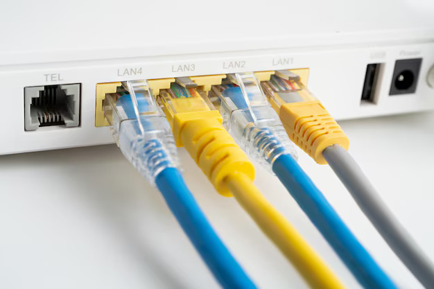
Introduction:
Even a single misstep in Ethernet Port Wiring or Ethernet Cabling can slash speeds by 90% or more, costing businesses thousands in downtime and productivity losses.In this guide, we’ll debunk common myths and reveal the 5 critical factors that determine whether your RJ45 wiring supports lightning-fast 10Gbps speeds or becomes a bottleneck. From selecting the right cable category to avoiding costly installation errors, discover how to future-proof your network infrastructure—no matter if you’re setting up a home office or a global data center.
1.Key Factor 1: Cable Types & Specifications
1.1 Cable Category Comparison
|
Cable Type |
Max Bandwidth |
Transmission Distance |
EMI Resistance |
Use Cases |
|
Cat5e |
1 Gbps |
100 m |
Basic UTP/STP |
Home/Small Office Networks |
|
Cat6 |
10 Gbps |
55 m |
Twisted Pair + Cross-Skeleton |
Enterprise Gigabit Networks |
|
Cat6a |
10 Gbps |
100 m |
Fully Shielded (F/UTP) |
Data Centers/High-Density Environments |
Technical Notes:
Cat6 reduces crosstalk via a cross-skeleton but requires a bending radius ≥4x cable diameter.
Cat6a supports 10Gbps up to 100m, ideal for future-proof Ethernet Cabling
1.2Shielded vs. Unshielded Cables
Shielded Cables (STP/FTP):
Advantages: Strong EMI resistance (attenuation reduced by 30-50%).
Use Cases: Industrial plants, near motors, or parallel power lines.
Unshielded Cables(UTP):
Advantages: Lower cost, easier installation.
Risks: Performance degradation in long-distance or high-interference environments.
Case Study: Amazon AWS Data Center Upgrade
An AWS data center mixing Cat6 and Cat5e cables achieved only 1.2Gbps throughput on a 10Gbps switch. Full replacement with Cat6a shielded cables boosted speeds to 9.8Gbps, proving the need for standardized high-grade RJ45 Wiring in data centers.
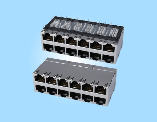
2.Key Factor 2: RJ45Wiring Errors & Crosstalk
2.1 RJ45Wiring Standards Comparison
|
Standard |
Wiring Order (Left to Right) |
Use Cases |
|
T568A |
White/Green, Green, White/Orange, Blue, White/Blue, Orange, White/Brown, Brown |
Legacy system compatibility |
|
T568B |
White/Orange, Orange, White/Green, Blue, White/Blue, Green, White/Brown, Brown |
Industry-standard Ethernet Port Wiring |
Crosstalk Mechanisms:
NEXT (Near-End Crosstalk): Interference between transmitting and receiving pairs at the same end.
FEXT (Far-End Crosstalk): Interference after long-distance signal propagation.
2.2Common Mistakes
Un-twisted Pairs: Crosstalk increases by 20% if untwisted beyond 2.5cm.
Wiring Mix-Ups: Swapping orange/green pairs can downgrade a 10Gbps link to 1Gbps.
Poor Termination: Loose connections cause signal reflection.
Solutions:
Use tools like the Klein Tools VDV226-112 to maintain twist integrity.
Test NEXT values ≥40dB with Fluke DSX-5000 for Ethernet Port Wiring compliance.
Case Study: Tesla Factory Network Outages
A Tesla gigafactory suffered 2-3 daily production line disruptions due to mixed T568A/B standards, costing over $5M annually. Full re-termination to T568B and crosstalk testing (NEXT ≥45dB) resolved the issue.
3. Key Factor 3: Cable Length & Signal Attenuation
3.1 Distance Limitations (100m Rule)
|
Speed |
Max Distance (Cat6) |
Attenuation Limit |
|
1 Gbps |
100m |
≤22dB |
|
10 Gbps |
55m |
≤19dB |
3.2 Long-Distance Solutions
|
Solution |
Use Case |
Cost |
|
Fiber + Converter |
>100m with high-speed Ethernet Cabling |
High |
|
Repeater/Switch |
Mid-point network extension |
Medium |
|
Speed Reduction |
Temporary low-cost workaround |
Low |
Practical Tips:
Home networks: Adopt star topology to minimize cable length.
Offices: Keep rack-to-desk distances ≤70m.
Case Study: London Metro Fiber Upgrade
London Metro deployed TP-Link MC200CM fiber-to-RJ45 converters to connect 150m stations, achieving stable 10Gbps speeds. Similar solutions now power Paris Metro and New York transit systems.
4. Key Factor 4: Termination Quality & Poor Connections
4.1 Crimping Standards
Wire Exposure: 1.2-1.5cm (Too long easy short circuit, too short contact is bad).
Insulation Piercing: Ensure RJ45 connector blades penetrate insulation.
4.2 Tools & Testing
Recommended Tools:
Ratcheting crimpers (e.g., Fluke Networks DTX-1800) for consistent pressure.
Testing Methods:
Time-Domain Reflectometry (TDR) for breakpoint detection (±1m accuracy).
Continuity tests to verify all 8 cores.
Case Study: NASA Mars Rover Delay
A NASA Mars rover experienced data transmission failures due to poor RJ45 termination, delaying the mission by 3 weeks. Re-crimping with Klein Tools VDV226-112 and TDR validation resolved the issue, leading to NASA’s Aerospace RJ45 Termination Standard (pressure tolerance ≤±5%).
5. Key Factor 5: Electromagnetic Interference (EMI) & Environmental Factors
5.1 Interference Sources
|
Type |
Sources |
Impact |
|
Conducted EMI |
Power lines, motors |
Signal waveform distortion |
|
Radiated EMI |
Fluorescent lights, Wi-Fi APs |
High bit error rates |
5.2Mitigation Strategies
|
Physical Isolation |
Cable Selection |
Standards |
|
Metal conduits (≥30dB shielding), 30cm separation from power lines |
F/UTP cables (40% attenuation reduction), fiber optics |
TIA/EIA 568-C.2 ISO/IEC 11801 |
Case Study: Siemens Smart Factory
A Siemens plant achieved 0.1% bit error rate (down from 20%) by upgrading to F/UTP cables, metal conduits, and optimized grounding (≤8Ω), boosting productivity by 15%.
Anticipate 3-5 year needs (e.g., 10Gbps, IoT).
Use star topology to limit cable runs ≤70m.
Bending radius ≥4x cable diameter (Cat6a ≥50mm).
Label cables with waterproof tags (e.g., Brother P-touch PT-D210).
TIA/EIA 568-C.2: Test 12 parameters including NEXT, attenuation, and return loss.
SO/IEC 11801 Ed2.0: EMI resistance validation for Ethernet Cabling.
Conclusion:
RJ45 Wiring remains the backbone of reliable Ethernet Cabling, but its performance hinges on careful cable selection, proper Ethernet Port Wiring, and rigorous testing. By addressing these five key factors, you can ensure networks operate at peak efficiency, even in demanding environments.