
This step-by-step guide will walk you through the complete process of making an RJ45 female connector—from selecting the appropriate wiring standard and essential tools to executing a clean termination and verifying the connection.
For dependable results, choose GLGNET’s Female RJ45 Modular Jack Connectors—engineered for high performance, compliant with CAT5e standards, and tested for over 750 insertion cycles to ensure lasting durability in every application.
Creating a reliable RJ45 female connector—commonly used in wall outlets, patch panels, or structured cabling systems—requires a few essential tools and components. Each item plays a critical role in ensuring a secure connection and stable, high-speed data transmission.
Want to ensure you're using the right RJ45 jack for your application?
https://www.glgnet.biz/selecting-the-correct-rj45-jack-connector
The RJ45 female connector serves as the primary interface between your Ethernet cable and the network infrastructure. These connectors are available in several formats, such as keystone jacks for wall plates or panel-mount jacks for use in rack-mounted systems. Internally, they use IDC (Insulation Displacement Contacts) to securely terminate each wire from the twisted-pair cable without requiring the insulation to be stripped, making the process faster and more reliable.
Next, you'll need an Ethernet cable that matches your network’s performance requirements. Cat5e cables are suitable for standard Gigabit Ethernet, while Cat6 or Cat6a cables provide higher data rates and improved shielding against electromagnetic interference—ideal for demanding environments. Be sure to select a cable type (e.g., UTP for unshielded, STP for shielded) that is compatible with your chosen connector.
Need optimal connectivity for high-speed networks? Learn how to match your Cat6A cable with the right connector in our expert guide:
https://www.glgnet.biz/how-to-choose-the-right-rj45-connector-for-cat6A-cable
A punch-down tool is essential for pressing each wire firmly into the corresponding slot on the jack. It establishes a secure electrical connection by forcing the conductor into the IDC terminal and often trims the excess wire at the same time. Some advanced models offer interchangeable blades and adjustable impact settings, allowing for greater flexibility and compatibility with various connector designs.
Before you can terminate the cable, you’ll need to strip away the outer jacket to expose the internal twisted pairs. A dedicated cable stripper is ideal, as it allows for clean, precise cuts without damaging the conductors inside. Alternatively, a utility knife can be used, though extra caution is required to avoid nicking or cutting the wires.
Finally, it’s important to follow a recognized wiring standard to ensure correct pinout and network functionality. Both T568A and T568B standards define the proper order of the eight color-coded conductors. While T568B is more widely used in commercial networks, T568A may be required for residential or government installations. Fortunately, most keystone jacks include printed diagrams for both standards to help you place each wire accurately.
Terminating a female rj45 connector properly is essential for maintaining a high-performance and reliable network. From selecting the correct wiring standard to making secure terminations and verifying connections, each step plays a key role in ensuring success. Here's how to do it right.
Before starting, choose a recognized wiring scheme—T568A or T568B. Both offer the same technical performance, but T568B is more commonly used in commercial environments, especially in North America. For consistency, always match the standard already used in your network. Mixing standards at each end of a cable will create a crossover connection, which may interfere with typical Ethernet setups.
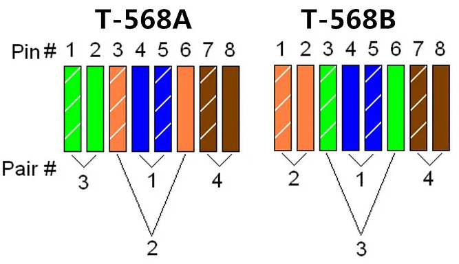
T568B Color Sequence:
White/Orange
Orange
White/Green
Blue
White/Blue
Green
White/Brown
Brown
Most female rj45 connectors include clear labeling for both T568A and T568B standards, making it easier to follow the correct sequence.
A successful termination begins with precise cable preparation. This step directly impacts both the electrical performance and mechanical stability of the final connection. Start by stripping approximately 1.5 to 2 inches (4–5 cm) of the outer jacket from the Ethernet cable using a cable stripper or a sharp utility knife. Exercise caution during this process—cutting too deeply can damage the insulation around the inner conductors, potentially leading to shorts, degraded signal quality, or long-term reliability issues.
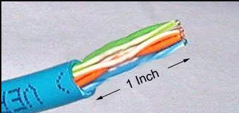
After removing the jacket, you'll reveal four twisted pairs of wires, totaling eight individual conductors. Each pair is color-coded for easy identification. To reduce the risk of signal interference and preserve the cable's inherent crosstalk protection, only untwist each pair as much as necessary—generally no more than half an inch. Then, gently straighten the wires with your fingers to prepare them for termination.
Once the wires are untwisted and aligned, arrange them side by side according to the color sequence specified by your chosen wiring standard (T568A or T568B). Maintaining this sequence precisely is crucial, as it ensures the correct pairing and signal routing required for proper Ethernet communication.
With the conductors properly aligned, you're ready to place them into the RJ45 jack. Most keystone jacks or modular panel jacks are clearly labeled with color-coded guides for both wiring standards. Take a moment to double-check that you're referencing the correct column for your selected scheme, as even a single misplaced wire can disrupt network performance.
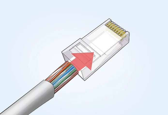
Carefully insert each wire into its corresponding slot. The exposed copper conductor should extend to the bottom of the channel, making full contact without being forced. The wires should slide in smoothly and lie flat within their slots—avoid overlapping, bunching, or twisting, as this can lead to poor contact or interference inside the jack.
Neatly loaded wires not only ensure proper electrical connections but also simplify the next step: the punch-down. Precision at this stage helps minimize rework and ensures a clean, professional result.
Once all eight conductors are properly seated, the next step is to secure them using a punch-down tool. This tool pushes the wire into the Insulation Displacement Contact (IDC) inside the jack, which slices through the insulation and establishes a reliable electrical connection with the copper core.
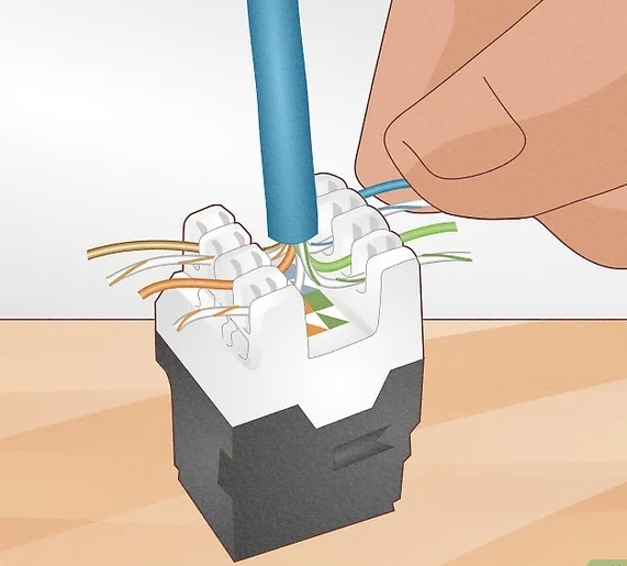
To execute this step, align the punch-down tool blade directly over the wire slot. Apply firm, steady pressure straight down until you hear or feel a distinct "click"—this indicates the wire is fully seated, and the connection has been made. Many punch-down tools are equipped with a built-in cutter that simultaneously trims the excess wire for a clean finish.
Repeat this process for each of the eight wires, being careful to keep the tool vertical and centered to prevent damaging the jack's internal structure. If your tool lacks a cutting function, use flush cutters or scissors to carefully trim any protruding wire ends, ensuring no sharp edges or loose strands remain.
After completing the electrical termination, it's important to physically secure the cable to the jack. This final mechanical step protects the internal wiring from strain, vibration, or accidental pulls that could weaken the connection over time.

Most RJ45 jacks come equipped with a clamp, hinged lid, or snap-in cap designed to hold the cable’s outer jacket in place. Close or fasten this component according to the jack’s design to engage the strain relief mechanism. This ensures that any physical stress is absorbed by the cable jacket, not the delicate internal conductors.
Once secured, give the cable a gentle but firm tug to confirm that it's properly held in place. A well-strained connector provides better durability and reliability, especially in environments where cables may be moved, bumped, or subjected to thermal expansion and contraction.
While optional in casual settings, testing the completed connection is strongly recommended to verify electrical integrity and prevent future troubleshooting headaches. Use a network cable tester or continuity checker to confirm that your termination meets industry standards.
Connect one end of the tester to the jack using a known-good patch cable, and the other end to the tester’s remote module or to a compatible port. The tester will run through a series of checks, including:
Pin-to-pin continuity, ensuring that each conductor is connected end-to-end
Correct wiring order, verifying alignment with the T568A or T568B standard
Detection of faults, such as open circuits, shorts, reversed pairs, or miswiring
If the test passes without any errors, your RJ45 jack is ready for deployment. If the tester flags an issue, revisit the termination process—check for misaligned wires, incomplete punch-downs, or reversed pairings—and make corrections as needed.
If the RJ45 jack is intended for a fixed installation, such as in a structured cabling system:
Snap the terminated jack into a compatible keystone wall plate or patch panel slot, ensuring it locks firmly into place without gaps or looseness.
Apply a clear label to the port to identify its destination or function, which helps streamline future maintenance and network management.
Want to dive deeper into choosing the right network connectors?
Discover how to select the perfect RJ45 jack connector:
https://www.glgnet.biz/selecting-the-correct-rj45-jack-connector
Learn what you need to know before choosing an SFP cage for your network device:
Still deciding between Cat5e and Cat6 RJ45 jacks? Check out this detailed comparison:
https://www.glgnet.biz/cat5e-vs-cat6-rj45-jacks-which-one-should-you-choose
Conclusion
Making an rj45 female to female connector may seem technical at first, but with the right tools, careful preparation, and attention to detail, the process becomes straightforward and highly repeatable. Whether you're wiring a single outlet or preparing a network rack for high-volume data transmission, proper termination ensures reliable performance, minimal signal loss, and long-term durability.